


Lithium Battery for Portable Blood Analyzers: OEM Runtime and Pack Design
For an OEM developing a portable blood analyzer, lithium battery pack design involves selecting the battery voltage, capacity, cell chemistry, BMS and enclosure. The battery needs to support the analyzer's operating cycle, sample processing, display, data communication and charging requirements.
This article explains lithium battery design for portable blood analyzers, including runtime calculation, cell selection, BMS configuration and OEM battery pack specifications.
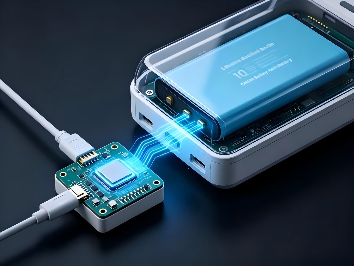
1. Battery Design Requirements for Portable Blood Analyzers
A portable blood analyzer may perform several operations during one testing cycle, including system startup, sensor initialization, sample preparation, measurement, data processing, display operation and wireless communication.
Power demand can change between these operating states. The battery should therefore be designed according to the analyzer's measured operating profile.
Battery design requirements may include:
Power output within the analyzer's required voltage range.
Capacity for the specified number of samples.
Peak current capability for startup and measurement.
Compatibility with the analyzer's charging system.
Battery state-of-charge monitoring.
Protection against abnormal electrical conditions.
An enclosure and connector that match the device structure.
Operation within the specified temperature range.
The battery is part of the analyzer's power system. Its design should be coordinated with the electrical, mechanical and software engineering teams.
2. Portable Blood Analyzer Battery Runtime Calculation
Battery runtime depends on energy consumption, usable battery capacity and operating conditions.
The basic energy calculation is:
Nominal Energy (Wh) = Battery Voltage (V) × Rated Capacity (Ah)
For example, a 14.8V 5Ah lithium-ion battery pack has:
14.8V × 5Ah = 74Wh
If the analyzer consumes an average of 10W, a theoretical runtime calculation is:
74Wh ÷ 10W = 7.4 hours
This calculation does not represent the measured operating time of the complete analyzer. Actual runtime can be affected by battery discharge characteristics, DC-DC converter efficiency, operating temperature, battery cutoff voltage and analyzer power management settings.
A system-level runtime calculation can be expressed as:
Estimated Runtime = Nominal Battery Energy × Usable Energy Factor × System Efficiency ÷ Average Load Power
For example, if a 74Wh battery pack has a usable energy factor of 85% and system efficiency is 90%:
74Wh × 0.85 × 0.90 = 56.61Wh
At an average load of 10W:
56.61Wh ÷ 10W = 5.66 hours
The final runtime should be confirmed through testing with the complete analyzer.
3. Lithium-Ion Chemistry Selection
Lithium-ion battery packs are used in portable medical equipment as rechargeable energy sources.
Battery chemistry selection depends on the analyzer's energy requirements, voltage range, dimensions, operating temperature, charging system and safety requirements.
Lithium-Ion NMC
Nickel manganese cobalt oxide, commonly referred to as NMC, is used in rechargeable battery packs.
NMC battery design involves factors such as:
Cell energy density.
Cylindrical or pouch-cell configuration.
Battery pack dimensions.
Discharge characteristics.
Operating temperature.
Charging requirements.
NMC packs require a BMS, cell protection and a charging system that match the selected cells.
Lithium Iron Phosphate
Lithium iron phosphate, or LiFePO4, is another lithium-ion battery chemistry.
LiFePO4 has a nominal cell voltage of approximately 3.2V, while many NMC cells have a nominal voltage of approximately 3.6V to 3.7V.
A LiFePO4 pack can be considered when the equipment's electrical architecture and mechanical structure support the required voltage characteristics and physical configuration.
The selected chemistry should correspond to the device's voltage range, charging method, available installation space and operating requirements.
4. Battery Voltage and Capacity
Battery voltage should correspond to the analyzer's electrical architecture.
Lithium-ion battery pack configurations may include:
1S: approximately 3.6V to 3.7V nominal for many NMC cells.
2S: approximately 7.2V to 7.4V.
3S: approximately 10.8V to 11.1V.
4S: approximately 14.4V to 14.8V.
6S: approximately 21.6V to 22.2V.
The actual nominal voltage depends on the cell chemistry and cell manufacturer's specifications.
For LiFePO4 cells, configurations may include:
4S: approximately 12.8V.
8S: approximately 25.6V.
The analyzer's input voltage range, DC-DC converter and charger must be compatible with the selected battery configuration.
Example Battery Specification
| Parameter | Example Specification |
|---|---|
| Battery chemistry | Lithium-ion NMC |
| Nominal voltage | 14.8V |
| Rated capacity | 5Ah |
| Nominal energy | 74Wh |
| Continuous discharge current | To be defined by load testing |
| Peak discharge current | To be defined by startup requirements |
| Charging method | Manufacturer-specified CC/CV profile |
| BMS | Overcharge, over-discharge, overcurrent and temperature protection |
| Communication | Fuel gauge, SMBus, CAN or other required interface |
| Enclosure | Custom design |
| Connector | Custom selection |
| Application | Portable blood analyzer |
This specification is an engineering example. The final voltage and capacity should be determined from the analyzer's measured power profile.
5. Battery Pack Design for Medical Device Integration
Portable blood analyzers may have limited internal installation space. The battery may be positioned beside the sample chamber, sensor module, display, processor board and other electronic components.
Battery pack design should consider the complete mechanical layout of the analyzer.
Mechanical Design Requirements
A custom battery pack may include:
A molded or metal enclosure.
Custom cell arrangement.
Cell and component fixation.
A locking connector.
Mounting brackets.
A removable battery interface.
A charging port.
A battery label.
A service access panel.
The battery should be secured to prevent movement that could affect cells, wiring or connectors during normal handling and transport.
The enclosure should be evaluated for heat dissipation and cleaning requirements.
If the analyzer is used in a clinical environment, the OEM should define requirements for battery compartment cleaning, maintenance and access.
6. BMS Design
The battery management system monitors battery conditions and controls protection functions.
BMS functions may include:
Overcharge protection.
Over-discharge protection.
Overcurrent protection.
Short-circuit protection.
Temperature monitoring.
Cell balancing.
State-of-charge estimation.
Battery voltage and current monitoring.
Communication with the analyzer.
The communication interface may include SMBus, I²C, CAN, RS485 or another protocol defined by the analyzer's electronic architecture.
The battery manufacturer should confirm the communication protocol, data format and required parameters with the medical device OEM before development.
7. Charging System Compatibility
The charging system should be designed together with the battery pack.
For lithium-ion batteries, charging voltage and current must correspond to the selected cell configuration.
A typical lithium-ion charging profile uses constant-current and constant-voltage stages. The charging voltage depends on the battery chemistry and series configuration.
For example, a 4S NMC pack with a nominal voltage of 14.8V may use a charging voltage of 16.8V when the selected cells have a 4.2V maximum charging voltage per cell.
The charger must be compatible with the battery BMS and the analyzer's power management system.
8. Battery Runtime Testing
Runtime should be verified using the complete analyzer.
A battery pack may pass a capacity test while the measured runtime in the analyzer differs from the calculated value. Differences can result from the analyzer's load profile, DC-DC conversion efficiency, temperature and power management behavior.
A validation process may include:
Fully charge the battery according to the specified charging method.
Install the battery in the analyzer.
Record the initial battery voltage and state of charge.
Operate the analyzer using a defined test procedure.
Record current, voltage and operating time.
Monitor battery temperature.
Record the analyzer's operating state.
Continue until the specified battery cutoff condition.
Repeat the test under the required conditions.
The test procedure should represent the intended operating conditions of the analyzer.
9. Safety and Compliance
Medical battery compliance depends on the battery design, intended use, target market and applicable standards.
Battery-related standards and documents may include:
UN38.3 transportation testing.
MSDS documentation.
IEC 62133-2.
IEC 62619.
IEC 60601-1.
UL 1642.
The applicable requirements should be confirmed before production and shipment.
The battery manufacturer should provide relevant battery-level test reports and technical documentation required by the OEM.
10. OEM/ODM Battery Pack Development Process
For a portable blood analyzer, the battery pack can be developed according to the analyzer's electrical and mechanical specifications.
An OEM/ODM development process may include the following stages.
Step 1: Collect Device Requirements
The OEM provides information such as:
Input voltage range.
Average operating power.
Peak current.
Required operating time.
Charging method.
Battery installation space.
Connector requirements.
Operating temperature.
Communication protocol.
Required protection functions.
Step 2: Battery Configuration
The battery manufacturer evaluates:
Cell chemistry.
Series and parallel configuration.
Rated voltage.
Rated capacity.
Cell dimensions.
BMS architecture.
Protection requirements.
Step 3: Prototype Development
A prototype battery pack is produced for integration testing.
The prototype can be evaluated for:
Electrical compatibility.
Mechanical fit.
Connector position.
Battery runtime.
Charging behavior.
Temperature performance.
BMS communication.
Step 4: Sample Testing
The battery is tested together with the analyzer under defined operating conditions.
Test data can be used to adjust the battery configuration, BMS parameters, enclosure structure or connector design.
Step 5: Production Preparation
After the battery design is confirmed, production documentation can be prepared, including:
Battery specifications.
Cell specifications.
BMS parameters.
Wiring diagrams.
Assembly drawings.
Test requirements.
Inspection standards.
Packaging requirements.
Step 6: Mass Production
Production follows the approved battery specification and quality-control requirements.
Each battery pack can undergo electrical testing, protection-function testing and final inspection according to the agreed quality plan.
11. Battery Specification Checklist for Portable Blood Analyzer OEMs
Before requesting a quotation from a battery manufacturer, the medical device OEM should prepare the following information:
| Requirement | Information to Provide |
|---|---|
| Application | Portable blood analyzer |
| Battery chemistry | NMC, LiFePO4 or other selected chemistry |
| Nominal voltage | Device requirement |
| Capacity | Required Ah or Wh |
| Average power | W |
| Peak power | W |
| Continuous current | A |
| Peak current | A |
| Operating time | Hours or testing cycles |
| Charging voltage | V |
| Charging current | A |
| Battery dimensions | L × W × H |
| Connector | Type and position |
| Communication | SMBus, I²C, CAN, RS485, etc. |
| Operating temperature | Required range |
| Storage temperature | Required range |
| BMS functions | Protection and monitoring requirements |
| Enclosure | Plastic, metal or custom structure |
| Compliance | Applicable market and standards |
| Quantity | Prototype and production volume |
Providing these details allows the battery manufacturer to evaluate the electrical, mechanical and manufacturing requirements before developing the battery pack.
12. Conclusion
A lithium battery for a portable blood analyzer should be designed according to the analyzer's measured power profile, voltage range, operating cycle, mechanical structure and charging system.
Key design parameters include battery chemistry, cell configuration, voltage, capacity, discharge current, BMS functions, communication interface, enclosure and connector.
Runtime calculations can provide an initial engineering reference. Complete-device testing is required to verify the operating time under defined conditions.
For medical device OEMs, battery development may include requirement analysis, cell selection, battery configuration, BMS development, mechanical design, prototype production, device integration, testing and production preparation.
A custom OEM/ODM battery pack specification should be established before mass production so that the battery and analyzer can be evaluated as an integrated system.

 E-mail


 +86 13510702894