


What Does a Battery Management System Actually Manage? A Technical Guide
A Battery Management System (BMS) is an electronic system used to monitor and control the operating conditions of a rechargeable lithium battery pack. It monitors cell voltage, current, temperature, battery status, and other parameters. Depending on the application, a BMS can also provide cell balancing, protection functions, SOC and SOH estimation, and communication with the host device.
For custom lithium battery packs used in AGVs, industrial robots, medical equipment, electric bicycles, power tools, and energy storage systems, BMS design needs to match the electrical, mechanical, and operating requirements of the equipment.
So, what does a BMS actually manage?
In practical battery engineering, a BMS manages several key areas: cell voltage, current, temperature, battery state, cell balancing, power paths, and communication.
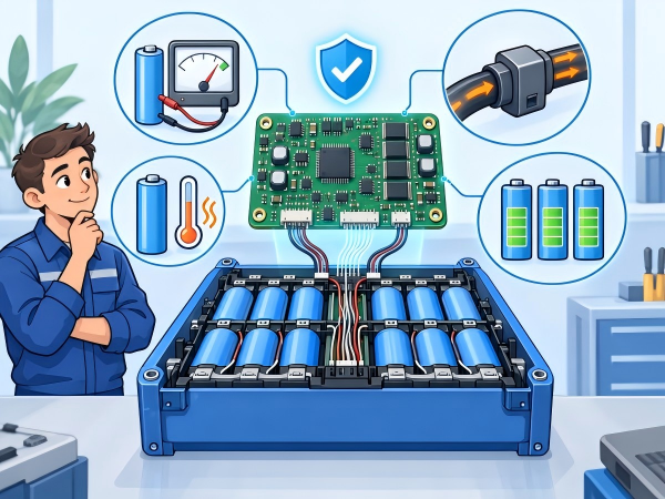
1. Cell Voltage Management
A lithium battery pack can contain multiple cells connected in series and parallel. For example, a 13S4P battery pack contains 13 series groups, with four cells connected in parallel in each group.
During charging and discharging, individual cell groups may have different voltage levels. The total battery voltage alone cannot show the condition of every cell group.
The BMS uses cell voltage sensing circuits to monitor individual series groups.
Overcharge Protection
When a cell group reaches its configured charging protection threshold, the BMS can stop or limit charging according to the system design.
The protection threshold depends on the cell chemistry and cell manufacturer's specifications. Lithium iron phosphate (LiFePO4) and NMC cells, for example, have different voltage ranges.
Over-Discharge Protection
During discharge, one cell group may reach its lower voltage limit before the others. The BMS monitors the cell voltage and can disconnect or limit the discharge path when the configured protection condition is reached.
This function is important for equipment that uses multiple series-connected cells.
2. Current Management
Battery capacity and battery current capability are different specifications.
For example, a 48V 50Ah battery has a nominal energy value of:
48V × 50Ah = 2400Wh
However, the battery cannot automatically provide any current required by a 48V device.
The BMS monitors charging and discharging current through a shunt resistor, Hall-effect sensor, or another current sensing method.
It can identify conditions such as:
Charging overcurrent
Discharging overcurrent
Short circuit
Excessive current duration
Abnormal current changes
The BMS can then disconnect the power path, generate a fault signal, or send status information to the host controller.
For AGVs, robots, forklifts, and other motor-driven equipment, the BMS design should consider startup current, acceleration current, continuous current, and regenerative current.
3. Temperature Management
Temperature affects battery charging, discharging, internal resistance, and operating conditions.
A BMS can use NTC sensors or other temperature sensors to monitor the battery pack.
Sensors may be installed:
Between cell groups
Near high-current connections
Near MOSFETs
Inside the battery enclosure
At other locations identified during thermal testing
The BMS can use temperature information to control charging or discharging according to configured limits.
For example, the charging temperature range may be different from the discharging temperature range. Equipment used outdoors or in cold environments may also require low-temperature charging control or battery heating.
Temperature protection parameters should be determined according to the cell datasheet, battery structure, and application conditions.
4. SOC Management
SOC stands for State of Charge and represents the estimated remaining battery charge.
A simple calculation can be expressed as:
SOC = Remaining Capacity ÷ Reference Capacity × 100%
However, a BMS normally cannot determine SOC from voltage alone.
Battery voltage changes with:
Charge and discharge current
Temperature
Cell chemistry
Battery aging
Load conditions
Resting time
For this reason, BMS designs may use coulomb counting, voltage information, temperature data, battery capacity parameters, and other algorithms to estimate SOC.
For equipment that displays battery level or remaining runtime, SOC calculation should be tested under actual operating conditions.
5. SOH Management
SOH means State of Health. It describes the battery's condition relative to a reference state.
One method is to estimate SOH from capacity retention.
For example, if a battery originally has a reference capacity of 100Ah and its measured capacity becomes 80Ah:
SOH = 80Ah ÷ 100Ah × 100% = 80%
Depending on the BMS design, SOH estimation may also consider internal resistance, cycle count, capacity changes, and operating history.
When selecting a BMS for an OEM project, it is useful to confirm how SOH is calculated and whether battery data can be accessed through communication software.
6. Cell Balancing
Cells connected in series can develop voltage differences during operation.
The BMS can use a balancing function to manage differences between cell groups.
Passive Balancing
Passive balancing uses resistors to dissipate energy from cell groups with higher voltage.
The circuit is relatively simple, but the energy is converted into heat.
Active Balancing
Active balancing transfers energy between cell groups using circuits such as capacitors or inductors.
This type of design involves additional circuit components and control logic.
Balancing cannot repair a cell with abnormal capacity or internal resistance. Cell selection, cell matching, and BMS balancing should therefore be considered together during battery pack development.
7. Charge and Discharge Path Control
A BMS also manages the electrical path between the battery, charger, and equipment.
Common components include:
MOSFETs
Contactors
Relays
Fuses
Pre-charge circuits
For small and medium-power battery packs, MOSFETs are commonly used as electronic switches.
For larger battery systems, contactors may be used to control the main power path.
Equipment with large DC bus capacitors may require a pre-charge circuit. The pre-charge process gradually charges the input capacitors before the main contactor closes, reducing the initial current surge.
The selection of MOSFETs, contactors, fuses, and pre-charge components needs to consider voltage, current, thermal conditions, and system architecture.
8. BMS Communication
A BMS can communicate battery information to the host equipment.
Common interfaces include:
| Interface | Typical Application |
|---|---|
| CAN | AGVs, robots, industrial vehicles |
| UART | Embedded equipment |
| RS485 | Industrial equipment |
| SMBus | Smart battery systems |
| I²C | Internal electronics |
Depending on the communication protocol, the BMS may transmit:
Battery voltage
Charge and discharge current
SOC
SOH
Cell voltage
Temperature
Charging status
Discharging status
Fault codes
Battery identification information
For a custom battery project, the communication protocol should be defined during the design stage so that the BMS and host controller can be tested together.
9. What Does a Custom BMS Need to Match?
A BMS should be designed according to the battery pack and equipment.
Important parameters include:
Electrical
Nominal voltage
Full-charge voltage
Capacity
Continuous discharge current
Peak discharge current
Charging current
Cell chemistry
Series and parallel configuration
Mechanical
Battery dimensions
Installation space
Connector position
Cable length
Enclosure design
Mounting method
Waterproofing requirements
Functional
Overcharge protection
Over-discharge protection
Overcurrent protection
Short-circuit protection
Temperature protection
Cell balancing
SOC
SOH
CAN/UART/RS485 communication
Environmental
Operating temperature
Charging temperature
Storage temperature
Humidity
Vibration
Waterproofing requirements
These parameters help the battery engineering team select the cell configuration, BMS architecture, electrical components, and mechanical structure.
10. BMS Design for OEM/ODM Lithium Battery Packs
For a custom lithium battery pack, BMS development should be considered together with cell selection, battery structure, charger compatibility, wiring, connectors, and host equipment.
For example:
AGV battery: CAN communication, motor current, charging control, temperature monitoring.
Medical equipment battery: SOC display, alarm signals, charging management, and equipment communication.
E-bike battery: compact structure, cell protection, temperature monitoring, and communication functions.
Industrial robot battery: peak current, power path control, communication, and operating temperature.
Energy storage battery: capacity monitoring, temperature management, communication, and maintenance data.
A custom BMS allows these requirements to be defined according to the actual battery application instead of using the same configuration for every device.
11. How Yizhan Electronics Supports Custom BMS Development
Dongguan Yizhan Electronics Technology Co., Ltd. provides lithium battery pack OEM/ODM services for equipment applications.
The battery development process can cover:
Cell selection
Series and parallel configuration
Battery pack electrical design
Custom BMS functions
CAN, UART, and RS485 communication
Battery structure design
Connector and cable selection
Prototype production
BMS function testing
Battery pack testing
Mass production
For projects involving AGVs, robots, medical equipment, electric bicycles, industrial tools, and other devices, the battery engineering team can review the equipment requirements and develop a battery pack configuration around the required voltage, capacity, current, dimensions, temperature range, and communication protocol.
Conclusion
A BMS manages more than battery voltage.
It monitors cell voltage, current, temperature, SOC, SOH, cell balancing, power paths, and communication. These functions work together to control the operating conditions of a lithium battery pack.
For OEM/ODM projects, BMS design should start with the actual equipment requirements. Cell chemistry, electrical parameters, mechanical dimensions, operating environment, charger, and communication protocol all need to be considered during development.
A clearly defined BMS specification also provides a practical foundation for prototype testing, system integration, and battery pack production.

 E-mail


 +86 13510702894