



How to Design a Custom Lithium Battery Pack for Your Equipment
A custom lithium battery pack should be specified according to the equipment it powers.
The design needs to address voltage, current, energy, installation, charging and protection. Communication and service requirements may also apply.
This guide explains how to prepare a battery specification. It does not provide instructions for assembling cells or modifying a finished pack.
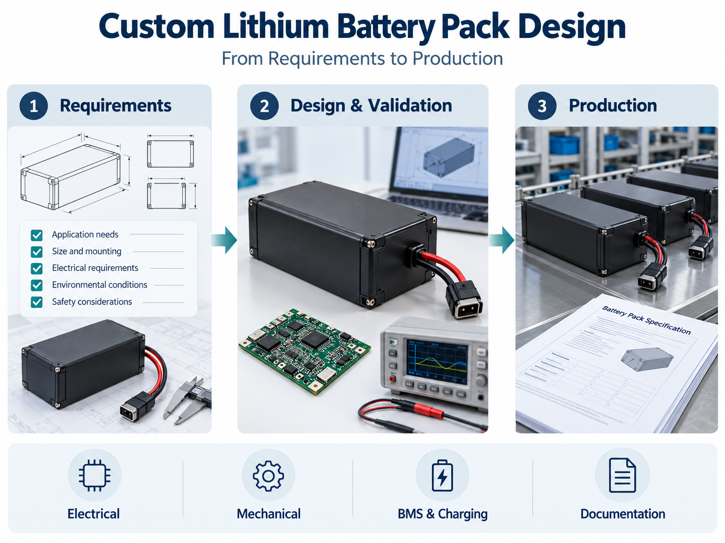
1. Define the Equipment Application
Document:
Equipment function.
Operating location.
Task duration.
Simultaneous loads.
Charging schedule.
Installation method.
Maintenance procedure.
Storage conditions.
Destination markets.
Include standby periods if circuits remain powered between tasks.
Separate confirmed requirements from assumptions that still need testing.
2. Record the Load Profile
List every device powered by the battery, including motors, sensors, computers, displays and accessories.
Measure battery-side voltage and current during the operating sequence.
| Operating State | Information to Record |
|---|---|
| Startup | Current, duration and voltage response |
| Normal operation | Power consumption and task duration |
| Actuator operation | Load profile and repetition |
| Standby | Consumption and duration |
| Shutdown | Power and time required |
Record equipment settings, payload, software and environmental conditions.
Component ratings alone do not describe the complete equipment’s consumption.
3. Specify the Voltage Range
Define:
Nominal voltage.
Full-charge voltage.
Normal discharge endpoint.
Equipment input limits.
Voltage behavior during transient loads.
Undervoltage response.
Check controllers, converters, displays and accessories.
Cell chemistry and series configuration determine the battery’s voltage characteristics. Batteries carrying the same nominal voltage label may have different charging limits.
4. Determine Task Energy
Calculate energy for each operating stage:
Energy (Wh) = average battery-side power (W) × time (h)
For example, a 60W average battery-side load operating for two hours uses approximately 120Wh.
This example explains the calculation. It does not establish the battery size for a specific product.
The specification should also account for:
Permitted operating window.
Temperature conditions.
Shutdown or return reserve.
Battery condition at the service endpoint.
Defined task variations.
Do not add conversion losses again if they are already included in battery-side measurements.
Nominal energy can be estimated using:
Nominal energy (Wh) = nominal voltage (V) × capacity (Ah)
Usable energy requires verification under stated conditions.
5. Define Current Requirements
Specify continuous and transient current separately.
For each transient, record:
Magnitude.
Duration.
Repetition rate.
Temperature.
State of charge.
Review the complete electrical path through cells, interconnections, BMS components, protective devices, cables and connectors.
Capacity does not establish current capability.
If the equipment returns energy during braking or deceleration, define the associated charging current and system response.
6. Identify the Cells
Document:
Chemistry.
Manufacturer and model.
Capacity measurement conditions.
Charge and discharge limits.
Temperature limits.
Dimensions.
Supporting documents.
Cell format and capacity alone do not establish suitability.
Cycle-life statements need test conditions and an endpoint. They should not be converted into guaranteed years of equipment service.
Define how cell substitutions will be reviewed.
7. Prepare Installation Drawings
Show:
Available space and tolerances.
Mounting points.
Orientation.
Mass limit.
Connector positions.
Cable routes.
Removal path.
Service access.
The installation envelope must accommodate insulation, electronics, wiring and structural parts.
For removable packs, document insertion, retention and removal. Verify these procedures in the equipment.
8. Specify BMS Functions
Depending on the design, functions may include:
Voltage monitoring.
Current measurement.
Temperature sensing.
Charge and discharge protection.
Cell balancing.
State-of-charge reporting.
Communication.
Sleep and wake-up.
Fault records.
Define thresholds, timing, actions and recovery conditions.
Keep normal operating limits separate from protective disconnection thresholds. Settings must follow the approved cell, component and system requirements.
State-of-charge and state-of-health outputs require defined calculation methods and validation. Their availability should not be assumed.
9. Define Connectors and Communication
Record:
Connector and mating-part numbers.
Pin assignments.
Polarity.
Cable type and length.
Strain relief.
Connection sequence.
Signal functions.
If communication is required, provide the host protocol.
Define messages, units, scaling, byte order, update intervals and timeouts.
An interface name such as CAN or RS485 does not establish compatibility with the host.
10. Confirm the Charging Arrangement
Specify:
Approved charger or charging-source requirements.
Charging voltage and current.
Temperature limits.
Termination behavior.
Connector and polarity.
Communication.
Fault response.
If equipment operation during charging is required, document the power path and validate that mode.
For docking systems, include alignment, contact engagement and charging permission.
Connector fit alone does not establish charging compatibility.
11. Document Environmental Conditions
Describe exposure during operation, charging, storage and handling.
Consider:
Temperature.
Adjacent heat sources.
Airflow.
Moisture and condensation.
Dust.
Cleaning agents.
Vibration and shock.
Sunlight.
Measure temperatures in the intended installation.
If a protection rating is required, identify the assembly and test conditions. Materials or seals alone do not establish a rating.
12. Define Service-Life Requirements
Document the conditions behind cycle-life requirements:
Charging profile.
Discharge profile.
Depth of discharge.
Temperature.
Rest periods.
Capacity-retention endpoint.
Also address calendar aging during storage and standby.
Define replacement criteria according to the equipment’s task, energy and power requirements.
13. Establish the Assessment Scope
Identify the applicable product, equipment and transport requirements.
Confirm with the relevant assessment body:
Standards and editions.
Product scope.
Model coverage.
Samples.
Documents.
Required reports or certificates.
Cell documentation does not automatically cover the pack. Battery documentation does not automatically cover the complete equipment.
Do not display certification marks without the relevant authorization.

 E-mail



 +86 13510702894
