



Custom Battery BMS Design: Protection, Communication and Integration
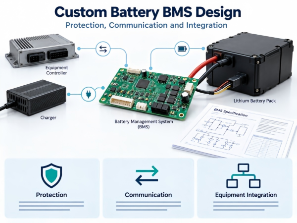
A battery management system, or BMS, measures battery conditions and performs the control functions included in its design.
For an OEM project, the specification should explain what the BMS monitors, how it responds to faults and how it interacts with the equipment.
A current rating or communication interface alone does not define these requirements.
1. Define the Battery and Equipment
Record:
Cell chemistry and model.
Series and parallel configuration.
Operating voltage range.
Continuous and transient current.
Charging requirements.
Temperature conditions.
Installation constraints.
Equipment interfaces.
Fault-response requirements.
Separate measured values, approved requirements and open decisions.
The design must remain within the operating limits of the selected cells and components.
2. Establish the Architecture
Identify the circuits responsible for:
Cell-voltage measurement.
Pack-voltage measurement.
Current measurement.
Temperature sensing.
Charge and discharge switching.
Protection.
Communication.
Auxiliary power.
Data storage, if required.
Some designs place these functions on one board. Others distribute them across assemblies.
Document the connections and responsibilities of each assembly.
3. Specify Measurement Requirements
Voltage
Define measurement points, range, accuracy, timing and fault detection.
In a series–parallel pack, a BMS may measure each parallel group as one voltage point. This does not establish individual monitoring of every cell within that group.
Current
Define the charge and discharge ranges, direction convention, accuracy, offset and sampling requirements.
Data reported to the host may have different timing from measurements used for protection. Document the distinction.
Temperature
Identify sensor type, quantity, location and fault response.
A sensor measures conditions at its location. Verify the placement in the intended enclosure.
4. Separate Operating Limits and Protection
| Function | Purpose |
|---|---|
| Operating limit | Defines permitted normal operation |
| Warning | Requests a defined response from the host or user |
| Protection | Performs an action when a specified condition is detected |
| Recovery | Defines when operation may resume |
The equipment should have a documented response to each warning and protective action.
Do not assume that every application can tolerate an immediate battery disconnection.
5. Define Protection Functions
Depending on the design, protection may address:
Cell overvoltage.
Cell undervoltage.
Charge overcurrent.
Discharge overcurrent.
Short circuit.
Charging temperature.
Discharging temperature.
Sensor faults.
For each function, record:
Detection method.
Threshold and tolerance.
Delay.
Action.
Reporting.
Recovery condition.
Review the measured load before changing protection settings. Settings must follow the approved cell, component and system limits.
6. Review the Power Path
The electrical path includes switching components, protective devices, interconnections, cables and connectors.
Specify:
Voltage and current requirements.
Switching sequence.
Thermal conditions.
Protection coordination.
Connection requirements.
Fault response.
A BMS current rating does not establish the current capability of the complete battery pack.
7. Define Precharge if Required
Equipment input capacitors may draw transient current when connected to the battery.
Where precharge is used, document:
Connected capacitance.
Initial voltage conditions.
Circuit arrangement.
Component energy limits.
Completion criteria.
Timeout.
Main-switch sequence.
Fault handling.
Precharge requires the relevant hardware and validation. Firmware alone cannot provide a missing power circuit.
8. Document Communication
For the selected interface, define:
Electrical requirements.
Communication settings.
Messages or register addresses.
Units and scaling.
Byte order.
Update intervals.
Timeouts.
Fault definitions.
Command permissions.
Protocol version.
An interface such as CAN or RS485 does not establish compatibility with a particular host.
Test the BMS with the intended controller, charger and display.
9. Assign Command Permissions
Identify which device may request:
Charging.
Discharging.
Sleep.
Wake-up.
Fault clearance.
Parameter changes.
Firmware updates.
Host commands should operate within the approved protection architecture.
Define the handling of conflicting, incomplete and unauthorized requests.
10. Define Communication-Loss Behavior
Specify:
When data becomes stale.
Timeout duration.
Local BMS response.
Host response.
Reconnection behavior.
The required action depends on the equipment and its fault analysis.
Local protection must function according to the battery design when host communication is unavailable.
11. Coordinate Charging
Document the responsibilities of the BMS, charger and host.
Include:
Charging voltage and current.
Temperature restrictions.
Charge permission.
Operating-limit messages.
Termination.
Fault response.
Disconnection behavior.
BMS protective disconnection should not serve as routine charge termination.
Where regenerative charging occurs, assess the current profile and system response when the battery cannot accept energy.
12. Specify Balancing
If balancing is included, define:
Method.
Control basis.
Activation conditions.
Current.
Scheduling.
Temperature limits.
Stop conditions.
Status reporting.
Balancing manages charge distribution among series positions. It does not repair damaged cells or make cell capacities identical.
Verify its operation under the intended charging schedule.
13. Define SOC and SOH
State of charge, or SOC, is an estimate of charge condition.
State of health, or SOH, needs a stated definition. It may represent capacity retention, resistance or another documented indicator.
Specify:
Calculation basis.
Input data.
Initialization.
Update conditions.
Learning or calibration requirements.
Unavailable-data behavior.
Validation method.
Do not display an unsupported percentage solely because the host interface contains a field for it.
14. Define Operating States
| State | Information to Define |
|---|---|
| Active | Measurements, communication and control |
| Idle | Functions retained between tasks |
| Sleep | Entry conditions and powered circuits |
| Shipping, if supported | Purpose, activation and exit procedure |
| Fault | Permitted actions and recovery |
Record consumption under stated conditions and the allowed state transitions.
Sleep does not necessarily mean zero current.
15. Specify Fault Records
Where logging is required, define the information retained:
Event code.
Voltage.
Current.
Temperature.
Operating state.
Event count.
Time information.
Firmware and configuration identifiers.
Document memory capacity, overwrite rules, retention and retrieval.
Calendar timestamps require a time source. Do not assume the BMS maintains calendar time.

 E-mail



 +86 13510702894
