



Custom Battery Packs for Agricultural Equipment
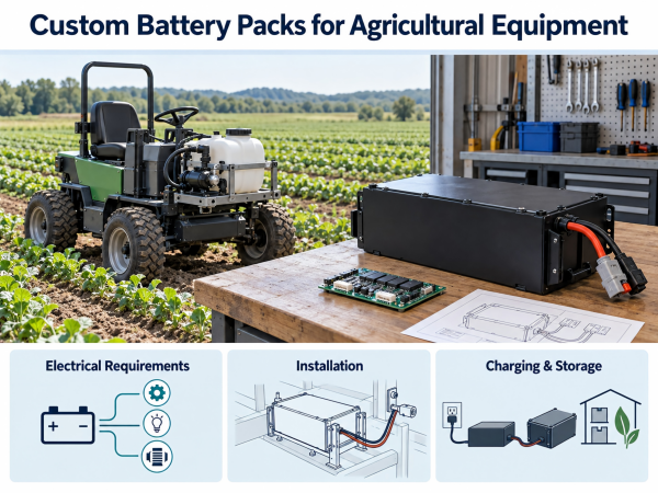
Agricultural equipment may use battery power for movement, pumping, sensing and control. The battery specification should reflect the machine’s tasks, electrical loads, installation and operating conditions.
Nominal voltage and capacity describe part of the battery. They do not establish compatibility with the complete equipment.
This guide outlines the information OEMs should document when developing a custom battery pack.
1. Define the Application
Applications may include:
Field monitoring instruments.
Irrigation controllers.
Portable spraying equipment.
Agricultural robots.
Electric utility carts.
Powered tools.
Material-handling equipment.
Record what the machine does, where it operates and how the battery is installed.
Equipment intended for potentially explosive atmospheres requires a separate review of applicable requirements. A general battery specification does not establish suitability for those locations.
2. Document the Working Schedule
Divide operation into defined stages:
Travel.
Active work.
Waiting.
Charging.
Transport.
Standby.
Storage.
Record the duration and frequency of each stage. Identify which values are measured and which are estimates.
For equipment carrying fluids, document the tank condition used during testing.
3. List the Electrical Loads
Include every device powered by the battery.
| Subsystem | Information to Record |
|---|---|
| Drive motors | Operating current, startup and terrain |
| Pumps | Pressure, duty cycle and startup |
| Actuators | Load, duration and frequency |
| Sensors | Supply requirements and activation |
| Computing | Startup, processing and standby |
| Communication | Transmission and idle consumption |
| Auxiliary circuits | Lighting, valves, fans and accessories |
Identify simultaneous loads.
Where practical, measure voltage and current at the battery output. Record the machine configuration and test conditions.
4. Specify Voltage Limits
Document:
Nominal voltage.
Full-charge voltage.
Normal discharge endpoint.
Voltage during load transients.
Equipment input limits.
Protection thresholds.
Check controllers, converters, displays, relays and accessories.
A shared nominal voltage label does not establish matching operating or charging limits.
5. Determine Task Energy
Calculate energy for each operating stage:
Energy (Wh) = average battery-side power (W) × duration (h)
Add the stage results to estimate task energy.
Then define the permitted operating window, temperature conditions, reserve requirement and service endpoint.
Do not add conversion losses again if they are already included in battery-side measurements.
Validate the energy requirement in the equipment. A calculation alone does not establish runtime.
6. Define Current Demand
Specify continuous and transient current separately.
For each transient, record:
Magnitude.
Duration.
Repetition rate.
Battery voltage.
Temperature.
State of charge.
Review the current path through cells, interconnections, BMS components, protective devices, cables and connectors.
Define the response to conditions such as a blocked pump or stalled mechanism.
7. Identify the Cells
Record:
Chemistry.
Manufacturer and model.
Voltage characteristics.
Capacity measurement conditions.
Charge and discharge limits.
Temperature limits.
Dimensions.
Supporting documents.
Capacity alone is not a cell selection criterion.
Document how proposed cell substitutions will be reviewed and approved.
8. Assess Temperature Conditions
Describe temperature exposure during operation, charging, transport and storage.
Consider sunlight, enclosure airflow, installation position and nearby heat sources.
Measure cell and component temperatures during the defined operating sequence.
Ambient temperature does not establish internal battery temperature.
9. Define Environmental Exposure
Identify possible contact with:
Rain.
Irrigation water.
Mud.
Dust.
Condensation.
Fertilizer.
Cleaning agents.
Agricultural chemicals.
Where relevant, record the substance, concentration, contact duration and cleaning method.
An ingress protection rating does not establish resistance to every chemical or cleaning procedure.
Specify the assembly and exposure conditions to be tested.
10. Document Mounting and Wiring
Provide drawings showing:
Dimensions and tolerances.
Mounting points.
Installation orientation.
Connector positions.
Cable routes.
Removal path.
Mass requirements.
Review cell restraint, fasteners, cable support and abrasion protection.
Define vibration and shock conditions for operation and transport.
Physical fit does not establish retention under those conditions.
11. Specify BMS Functions
Depending on the design, functions may include:
Voltage monitoring.
Current measurement.
Temperature sensing.
Charge and discharge protection.
Balancing.
Fault reporting.
Sleep and wake-up.
Recovery control.
Record thresholds, delays and actions.
Distinguish operating warnings from protective disconnection. Define how the equipment responds to each.
Essential local protection should not depend solely on host communication.
12. Define Communication
If communication is required, obtain the host protocol.
Document:
Interface.
Messages or registers.
Units and scaling.
Byte order.
Update intervals.
Timeouts.
Fault definitions.
Command permissions.
Firmware versions.
CAN or RS485 support alone does not establish compatibility.
Test the battery with the intended host, including missing or invalid messages.

 E-mail



 +86 13510702894
