



How to Design a Battery Pack for Limited Installation Space
In many battery-powered products, the available installation space is restricted by the equipment structure, mechanical components, and electrical interfaces. Designing a custom lithium battery pack for these applications requires consideration of battery cell dimensions, electrical configuration, BMS layout, enclosure structure, and thermal management.
Applications such as electric bicycles, electric scooters, AGVs, AMRs, service robots, medical equipment, and industrial devices may have specific requirements for battery dimensions and installation positions.
For OEM and ODM customers, a battery pack must meet the required voltage, capacity, and discharge current while fitting within the available installation space.
This article explains the engineering considerations involved in designing a custom battery pack for space-constrained applications.
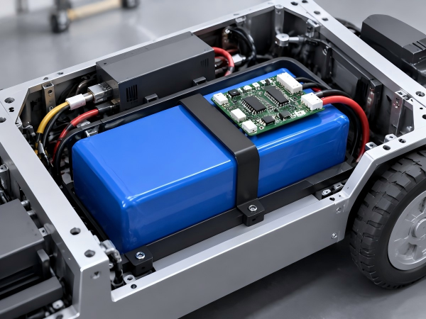
1. Define the Available Installation Space
The first step in custom battery pack development is to understand the available installation space inside the equipment.
Customers should provide the battery installation dimensions and relevant mechanical drawings before the design process begins.
Important information includes:
Maximum length, width, and height
Available battery compartment volume
Mounting position and orientation
Screw holes and fixing points
Connector installation positions
Cable routing space
Clearance from surrounding components
Space required for installation and removal
3D Mechanical Drawings
A 3D drawing of the battery compartment helps engineers understand the installation environment.
Common file formats include:
STEP
STP
IGES
SolidWorks files
2D PDF drawings
The surrounding equipment structure should also be considered.
For example, a robot battery compartment may be located between the motor controller, drive motors, and chassis structure. These components can restrict battery dimensions and cable routing.
Providing a 3D installation model allows the battery manufacturer to evaluate the available space before designing the enclosure.
2. Select Battery Cells According to Space Requirements
Battery cell selection directly affects the dimensions and internal structure of a battery pack.
Different cell formats have different dimensions, capacities, electrical characteristics, and assembly requirements.
Common lithium battery cell formats include cylindrical, prismatic, and pouch cells.
Cylindrical Lithium-Ion Cells
Cylindrical cells are used in electric bicycles, electric scooters, portable equipment, and industrial battery packs.
Common formats include:
18650
21700
These cells can be arranged in different series-parallel configurations according to the required voltage and capacity.
For example, a 36V 10Ah battery pack may use a 10S configuration with multiple parallel cells, depending on the selected cell capacity.
Cylindrical cells require cell holders, electrical connections, insulation materials, and mechanical support.
Prismatic LiFePO4 Cells
Prismatic LiFePO4 cells are used in industrial battery packs, AGVs, AMRs, and energy storage systems.
Their rectangular shape allows engineers to arrange cells in module structures.
The design should consider:
Cell length, width, and height
Terminal positions
Cell connection structure
Insulation requirements
Mechanical support
Cell expansion allowance where applicable
The selected cell model must fit the available compartment while meeting the required voltage and capacity.
Pouch Cells
Pouch cells have a flexible packaging structure and can be used in applications requiring specific battery dimensions.
Their design requires mechanical support, compression control where specified, terminal protection, and insulation.
Cell format selection should follow the application requirements, cell specifications, and available manufacturing processes.
3. Design the Battery Cell Arrangement
Battery cell arrangement determines how cells, electrical connections, insulation materials, and supporting structures fit inside the enclosure.
Series and Parallel Configuration
Lithium battery packs use series and parallel connections to achieve the required voltage and capacity.
Series connection (S): Determines the battery pack voltage.
Parallel connection (P): Increases battery capacity and current capability according to the electrical specifications of the selected cells.
Examples of common configurations include:
| Battery Configuration | Nominal Voltage | Typical Application |
|---|---|---|
| 10S Ternary Lithium-Ion | 36V | Electric bicycles |
| 13S Ternary Lithium-Ion | 46.8V | 48V-class electric mobility |
| 14S Ternary Lithium-Ion | 50.4V | 52V-class electric mobility |
| 8S LiFePO4 | 25.6V | 24V-class equipment |
| 16S LiFePO4 | 51.2V | Industrial equipment and ESS |
The nominal voltages shown are based on typical cell nominal voltages. Actual values depend on the selected cell model.
The number of parallel cells depends on the required capacity and current output.
Cell Layout
Depending on the enclosure dimensions, cylindrical cells may be arranged in different patterns.
Prismatic cells may also be positioned vertically or horizontally, subject to the cell manufacturer's installation requirements.
During layout development, engineers should evaluate:
Cell dimensions
Electrical connection paths
Insulation distances
Structural support
Heat transfer
Assembly access
Cable routing
The cell arrangement must satisfy the electrical and mechanical requirements within the available installation space.
4. Design a Compact BMS Layout
The Battery Management System (BMS) occupies part of the internal battery space.
For compact battery packs, the BMS PCB dimensions and installation position should be considered during the mechanical design stage.
PCB Dimensions
The BMS PCB should be designed according to the available installation space.
Possible arrangements include:
Flat PCB installation
Vertical PCB installation
Customized PCB shape
Separate power and control board structures
The selected arrangement depends on component layout, electrical connections, insulation, and heat generation.
BMS Component Placement
Power MOSFETs, capacitors, connectors, and other electronic components require appropriate installation space.
The design should consider electrical clearance, thermal conditions, and maintenance access.
Communication Interfaces
Some applications require CAN, UART, or RS485 communication.
The communication connector and wiring arrangement should be included in the mechanical layout.
For AGV and AMR battery packs, customers may also require temperature monitoring, SOC reporting, and fault information transmission.
NTC Temperature Sensors
Temperature sensors should be positioned according to the battery configuration and thermal design.
Their wiring routes should be included in the battery layout to avoid interference with cell connections and enclosure components.
5. Customize the Battery Enclosure
The battery enclosure determines the external dimensions and internal arrangement of the battery pack.
For space-constrained applications, enclosure development should be based on the equipment's installation structure.
Plastic Enclosures
Plastic housings are used in electric bicycles, electric scooters, portable devices, and industrial battery packs.
The enclosure can be designed according to the required dimensions, mounting structure, and connector positions.
Design considerations include:
Housing wall thickness
Internal support structures
Screw fixing points
Sealing structure
Insulation
Assembly access
Injection molding may require dedicated tooling when a new enclosure design is developed.
Aluminum Enclosures
Aluminum housings are used in industrial battery packs, robotics, and equipment requiring specific mechanical structures.
They can be manufactured using processes such as extrusion, CNC machining, and metal fabrication.
Design considerations include:
Wall thickness
Mounting brackets
Internal fixing structures
Heat transfer
Surface treatment
Electrical insulation
The enclosure structure should also meet the battery pack's mechanical and environmental requirements.
Customized Enclosure Shapes
Some applications cannot accommodate standard battery shapes.
In these cases, customized enclosure structures may be developed.
Examples include:
Long and narrow battery packs
Flat battery modules
L-shaped battery enclosures
Slide-in battery modules
Battery packs with curved external profiles
Battery housings integrated into equipment frames
The final design must account for cell dimensions, assembly processes, electrical safety, and thermal management.
6. Consider Connector Positions and Cable Routing
Connectors and cables occupy part of the available installation space.
Their positions should be confirmed during the battery mechanical design stage.
Common electrical interfaces include:
Charging connectors
Discharging connectors
CAN communication connectors
UART communication connectors
RS485 communication connectors
Temperature sensor connections
Multi-pin signal interfaces
For compact battery packs, the following details should be evaluated:
Connector Orientation
The connector should face the direction specified by the equipment installation structure.
Cable Bending Radius
Cables need sufficient bending space to avoid excessive mechanical stress.
Connector Accessibility
Charging and communication interfaces should remain accessible during normal operation.
Electrical Clearance
Power cables and signal wires should be arranged according to electrical insulation and safety requirements.
Waterproof Requirements
If the battery pack requires environmental protection, connector sealing and cable outlets should be included in the enclosure design.
7. Evaluate Thermal Management in Compact Battery Packs
Limited installation space can affect battery heat dissipation.
When multiple cells are installed inside an enclosure, heat generated during charging and discharging needs to be evaluated.
Thermal design considerations include:
Battery cell internal resistance
Continuous discharge current
Peak discharge current and duration
Cell arrangement
Enclosure material
BMS heat generation
Ambient temperature
Installation conditions
Passive Thermal Management
Passive thermal management uses heat conduction and natural convection.
Design options may include:
Aluminum enclosure structures
Thermal interface materials
Heat spreaders
Internal heat transfer paths
Active Thermal Management
For battery packs with specific cooling requirements, active thermal management may be evaluated.
Possible methods include:
Forced-air cooling
Liquid cooling
Dedicated cooling plates
The cooling method depends on the battery's thermal load, available space, and equipment design.
A compact battery pack must retain the required electrical insulation, mechanical support, and thermal protection.
8. Consider Battery Installation and Maintenance
A battery pack may fit within the equipment compartment but still present difficulties during installation or maintenance.
The mechanical design should consider the complete installation process.
Important points include:
Battery insertion direction
Removal clearance
Screwdriver access
Connector mating space
Cable connection sequence
Battery replacement procedure
Maintenance access to external interfaces
For removable battery systems, the design should also consider locking structures, positioning guides, and connector alignment.
For industrial robots and AGVs, battery replacement procedures may influence the equipment's maintenance workflow.
9. Electrical and Mechanical Verification
After completing the initial battery layout, the design should undergo electrical and mechanical verification.
Mechanical Verification
Mechanical checks may include:
Overall dimensions
Installation fit
Mounting hole positions
Connector alignment
Enclosure assembly
Cable routing
Mechanical clearance
Electrical Verification
Electrical checks may include:
Nominal voltage
Battery capacity
Continuous discharge current
Peak discharge current
Charging requirements
BMS protection functions
Communication functions
Thermal Verification
Thermal evaluation may include:
Temperature rise during continuous discharge
Temperature distribution
BMS component temperature
Operating temperature conditions
Charging temperature conditions
Prototype testing helps verify the design against the agreed project specifications.
10. Examples of Space-Constrained Battery Applications
Different equipment structures require different battery configurations and enclosure designs.
| Application | Design Considerations |
|---|---|
| Folding E-bike | Compact dimensions, folding structure, connector position |
| Electric Scooter | Frame integration, battery capacity, waterproof enclosure |
| Service Robot | Internal compartment dimensions, BMS position, cable routing |
| AGV | Battery module dimensions, mounting structure, discharge current |
| AMR | Removable battery design, communication interface, charging arrangement |
| Medical Equipment | Installation dimensions, electrical interfaces, applicable safety requirements |
| Power Tools | Enclosure dimensions, discharge current, mechanical support |
| Industrial Equipment | Mounting structure, electrical protection, maintenance access |
The final battery design depends on the equipment's technical requirements and installation environment.
11. Information Required for a Custom Compact Battery Pack
To develop a battery pack for limited installation space, OEM customers should provide the following information:
1. Available Installation Dimensions
Provide the maximum length, width, and height.
2. Mechanical Drawings
Provide 2D drawings or 3D STEP files showing the battery compartment and surrounding components.
3. Battery Specifications
Provide nominal voltage, capacity, charging voltage, and required energy.
4. Discharge Requirements
Specify continuous discharge current, peak current, and peak duration.
5. Battery Chemistry
Specify ternary lithium-ion, LiFePO4, or other required chemistry.
6. BMS Requirements
Confirm whether CAN, UART, RS485, NTC temperature monitoring, and customized protection functions are required.
7. Connector Requirements
Provide connector models, positions, and cable length requirements.
8. Environmental Conditions
Specify operating temperature, waterproof requirements, vibration conditions, and installation environment.
9. Production Quantity
Provide prototype quantity, initial order quantity, and estimated annual demand.
These details allow the battery manufacturer to evaluate cell selection, electrical configuration, enclosure structure, BMS layout, and prototype development requirements.
12. Custom Battery Pack Manufacturing at Dongguan Yizhan Electronics Technology Co., Ltd.
Dongguan Yizhan Electronics Technology Co., Ltd., operating under the First Power brand, provides OEM and ODM custom lithium battery pack development and manufacturing services.
Our battery pack business covers electric mobility, robotics, industrial equipment, and energy storage applications.
Our customization scope includes:
Ternary lithium-ion and LiFePO4 battery pack configurations
Customized voltage and capacity
Battery cell selection
BMS hardware and software customization
CAN, UART, and RS485 communication
Customized plastic and aluminum enclosures
Battery connector and wiring customization
NTC temperature monitoring
Battery pack assembly and testing
Technical documentation and certification project support
For battery projects with limited installation space, the development scope can include mechanical dimension evaluation, cell arrangement, BMS positioning, enclosure design, connector layout, and thermal management assessment.
The final design is determined according to the customer's equipment structure and confirmed battery specifications.
Conclusion
Designing a lithium battery pack for limited installation space requires coordination between electrical engineering, mechanical design, component selection, and thermal management.
Battery cell dimensions, series-parallel configuration, BMS layout, enclosure structure, connector positions, and maintenance access all affect the final battery design.
For OEM and ODM projects, providing installation drawings and electrical specifications at the beginning of development helps define the battery structure and technical requirements.
Whether you are developing an electric bicycle battery, a compact robot battery, an AGV battery module, or an industrial battery system, the battery pack should be designed according to the actual installation space and equipment requirements.
Looking for a custom lithium battery pack manufacturer?
Contact Dongguan Yizhan Electronics Technology Co., Ltd. (First Power) with your battery voltage, capacity, discharge current, available installation dimensions, and mechanical drawings.
Our team can review your project specifications and discuss a custom battery pack design based on your application requirements.

 E-mail



 +86 13510702894
