


Battery Communication: CAN, RS485 and BMS Protocol Guide
Choosing a UPS requires more than matching a product name to the power consumption of your equipment. Output capacity, battery energy, voltage compatibility and operating conditions all affect whether a backup system meets your needs.
The SDT-I500W-B300WH is a battery backup system from Shenzhen SDT New Energy Co., Ltd. According to its operation manual, it combines a lithium iron phosphate battery with pure sine wave AC output, 12V and 24V DC outputs, and a battery status display.
Two specifications are particularly important: the manual lists an AC output limit of 500VA and approximately 300Wh of battery energy. Although the model name contains “500W,” the specification table does not establish a 500W continuous real-power rating.
This guide explains the documented specifications, how to estimate backup runtime, and what to check before connecting equipment.
SDT-I500W-B300WH Specifications
The following information comes from the supplied product operation manual.
| Item | Specification listed in the manual |
|---|---|
| Manufacturer | Shenzhen SDT New Energy Co., Ltd. |
| Product model | SDT-I500W-B300WH |
| AC input | AC110V / AC220V, 50Hz / 60Hz |
| Input power | ≤400VA |
| System charging voltage | DC29.2V |
| Charging power | ≤300W |
| AC output | AC110V / AC220V, 50Hz / 60Hz |
| Output waveform | Pure sine wave |
| AC output capacity | ≤500VA |
| 12V DC output | 24W |
| 24V DC output | 30W |
| Battery chemistry | Lithium iron phosphate, LiFePO4 |
| Battery model | VDO-ES25.6V12AH |
| Nominal battery voltage | 25.6V |
| Rated battery capacity | 12Ah |
| Stated battery energy | Approximately 300Wh |
| Listed battery cycle life | 1,500 cycles |
| Display | 1.44 inches |
| Communication interface | Listed as USB / RS485 |
| Cooling | Fan cooling |
| Listed operating temperature | −10°C to 45°C |
| Dimensions, L × W × H | ≤312 × 218 × 90mm |
| Weight | Approximately 6.1kg |
The specification table lists both 110V and 220V, while the operating instructions specifically describe 110V use. Confirm the voltage and frequency of the supplied unit from its label and the manufacturer. Do not assume that both voltages are available simultaneously or that the unit automatically switches between them.
Does the Model Support 500W Loads?
The manual specifies an AC output capacity of ≤500VA. VA and W describe different electrical quantities:
VA, or volt-amperes, measures apparent power.
W, or watts, measures real power consumed by the load.
Their relationship is:
Real power (W) = Apparent power (VA) × Power factor
For example, a load drawing 500VA at a power factor of 0.8 consumes 400W of real power. This is an electrical calculation, not a confirmed 400W rating for this UPS.
Before selecting a load, obtain the manufacturer’s continuous output rating in watts and any supported startup or surge rating. The manual does not provide enough information to confirm compatibility with equipment simply because its label shows less than 500W.
Equipment with motors, compressors or other demanding startup behavior needs particular attention to starting current.
What Does the Approximately 300Wh Battery Mean?
The battery is rated at 25.6V and 12Ah. Its calculated nominal energy is:
25.6V × 12Ah = 307.2Wh
This is consistent with the manual’s description of approximately 300Wh.
Battery energy differs from output power. The output rating limits the load the UPS can support, while battery energy helps determine how long that load can operate.
The full nominal battery energy should not be treated as usable AC energy. Inverter losses, the UPS’s own consumption, battery condition, temperature and discharge cutoff can reduce the energy delivered to connected equipment.
How Long Can the UPS Provide Backup Power?
The manual does not include measured runtime at different loads. A basic estimate is:
Runtime (hours) ≈ Usable energy delivered to the load (Wh) ÷ Average load power (W)
Using 300Wh without accounting for losses gives the following theoretical reference values:
| Constant load | Runtime calculated from 300Wh before losses |
|---|---|
| 30W | 10 hours |
| 60W | 5 hours |
| 100W | 3 hours |
| 200W | 1.5 hours |
These figures are not measured product runtimes or load compatibility confirmations. Actual runtime will generally be lower because the calculation excludes conversion losses and system consumption.
For AC loads, a more detailed estimate is:
Runtime ≈ Nominal battery energy × Usable fraction × Inverter efficiency ÷ Average load power
For illustration, assume a 100W load, an 80% usable energy fraction and 90% inverter efficiency:
300Wh × 0.8 × 0.9 ÷ 100W ≈ 2.16 hours
The 80% and 90% values are assumptions, not specifications supplied for this model. A runtime test with the intended equipment is needed for a dependable backup plan.
Understanding the AC and DC Outputs
Pure Sine Wave AC Output
The manual identifies the AC output as pure sine wave. Before connecting equipment, verify its required input voltage, frequency, running load and startup demand.
A pure sine wave designation alone does not prove compatibility with every appliance or guarantee uninterrupted operation during a mains failure.
12V DC Output
The documented 12V output rating is 24W, corresponding to:
24W ÷ 12V = 2A
Confirm the connected equipment’s voltage requirement, current demand, connector size and polarity.
24V DC Output
The documented 24V output rating is 30W, corresponding to:
30W ÷ 24V = 1.25A
The same compatibility checks apply to the 24V port.
The manual does not specify a combined simultaneous-output limit. Do not add the AC and DC ratings together and assume the UPS can supply that total continuously.
Can It Keep a Computer or Network Device Running During an Outage?
The product is described as a UPS for power failure backup. However, the manual does not state its transfer time between mains and battery operation.
This matters because connected devices differ in how long they can tolerate an interruption. Equipment that requires uninterrupted operation should be checked against a confirmed transfer-time specification and tested with the actual UPS.
For computers, network devices and control equipment, confirm:
Input voltage and frequency compatibility.
Running power and apparent power.
Startup or transient demand.
Required backup duration.
Tolerance to the mains-to-battery transition.
The available manual does not establish suitability for life-support equipment or other safety-critical applications.
How to Start and Shut Down the UPS
Starting the Unit
The manual describes connecting the “AC INPUT” to a compatible mains supply. It states that the unit then provides output and charging functions. Operating the “AC ON/OFF” switch enables the battery output function.
Check the unit’s voltage label before connecting it. The manual also calls for professional guidance and prohibits unauthorized disassembly.
Shutting Down the Unit
According to the manual, a complete shutdown requires both:
Switching off the battery output using “AC ON/OFF.”
Disconnecting the AC input from mains power.
If mains remains connected, the manual states that output and battery charging can remain active even when battery output is switched off. The switch position alone should therefore not be treated as complete electrical isolation.
Reading the Battery Display
The 1.44-inch display shows battery operating information using these abbreviations:
| Display label | Meaning |
|---|---|
| CHG | Charging |
| STBY | Standby |
| DISCH | Discharging |
| SOC | State of charge percentage |
| TEMP | Temperature |
| VOL | Voltage |
| CUR | Current |
The manual states that, when mains is connected, activating the display keeps it illuminated. Without mains power, the display turns off approximately 30 seconds after activation.
State of charge helps monitor battery status, but it does not directly establish remaining runtime. Runtime also depends on the connected load and operating conditions.
Cooling and Installation Conditions
The unit uses fan cooling. The manual describes a brief fan self-check at startup, followed by temperature-controlled operation. The fan starts when the internal temperature reaches a set threshold and stops after the temperature falls.
Keep the fan inlet and outlet unobstructed. Restricted airflow can cause insufficient cooling and high-temperature faults.
The manual advises avoiding outdoor use and preventing water from entering the unit. Install it in a dry location and protect its electrical connections from inappropriate conductive objects.
Although the listed operating range is −10°C to 45°C, the manual does not separately define permissible battery charging temperatures. Confirm charging limits with the manufacturer before operating at temperature extremes.
Storage and Battery Maintenance
For long-term storage, the manual specifies the following:
Turn off the “AC ON/OFF” switch when the product is not in use.
Store it in a dry, cool location away from corrosive conditions.
Check battery charge before storage and bring it above 50% if necessary.
Recharge every three months during extended storage.
Arrange a comprehensive inspection before reuse after storage exceeding six months.
The manual lists a battery cycle life of 1,500 cycles but does not give the test temperature, charge and discharge rates, depth of discharge or end-of-life capacity threshold.
That number should therefore be presented as a manufacturer-listed specification, rather than a guaranteed service life in years or under every operating condition.
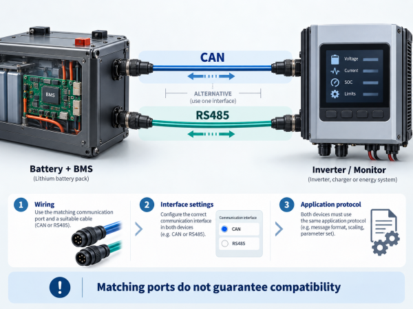
RS485 Communication: What Should Be Confirmed?
The manual lists a USB / RS485 communication interface and describes a USB-form connector associated with RS485.
This wording does not establish that the port supports USB charging, standard USB data communication or automatic compatibility with computer monitoring software.
Before integrating the UPS with another system, request the interface pinout, communication protocol, supported commands and any required adapter or software.
Frequently Asked Questions
Is the SDT-I500W-B300WH a LiFePO4 UPS?
Yes. The manual identifies the internal battery as lithium iron phosphate, with a nominal voltage of 25.6V and rated capacity of 12Ah.
Is it a confirmed 500W UPS?
The manual lists ≤500VA AC output. It does not establish a continuous 500W real-power rating. Confirm the watt rating and load limits with the manufacturer.
Can it supply both AC and DC equipment?
The manual documents AC, 12V DC and 24V DC outputs. Simultaneous-output capability and combined limits should be confirmed before connecting multiple loads.
Does it provide zero-transfer-time backup?
The manual does not specify transfer time. A zero-interruption claim is therefore unsupported by the supplied documentation.
Can it be used outdoors?
The manual advises avoiding outdoor use and preventing water ingress. It does not provide an outdoor protection rating.
What warranty does the manual list?
The manual states a 12-month warranty from the date the product leaves the factory. Confirm the applicable terms and start date when purchasing.
What to Confirm Before Ordering
The SDT-I500W-B300WH provides documented LiFePO4 battery storage, pure sine wave AC output and two DC output voltages. Whether it meets a particular backup requirement depends on the supplied voltage configuration, confirmed watt rating, transfer time and tested runtime.
Before ordering, provide the supplier with the equipment’s running load, startup demand, required voltage and target backup duration. Request confirmation of those requirements against the actual unit, especially where uninterrupted operation is important.
Source: the supplied SDT-I500W-B300WH operation manual, Rev. A0. Product specifications above are manufacturer-listed values. Runtime examples are calculations, not independent test results.
Related articles
-
2026-09-22
How to Customize a Robot Battery Pack...



 E-mail


 +86 13510702894