


How to Specify an E-Bike Battery Pack for an OEM Project
An e-bike battery pack must work with the bicycle’s controller, charger, display and mounting system. Nominal voltage and capacity describe part of the battery, but they do not establish system compatibility.
For an OEM project, the specification should also define current demand, installation dimensions, operating conditions, communication and test requirements.
This guide explains the information to document when sourcing or developing an e-bike battery pack.
Source review date: October 12, 2026. The calculations below are planning examples. Final specifications require confirmation using the selected components, system tests and applicable market requirements.
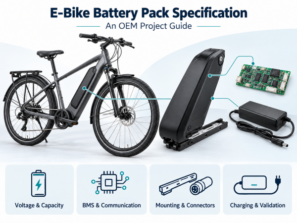
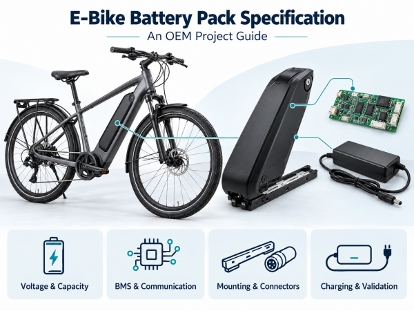
1. Define the Application and Operating Conditions
Begin with the bicycle’s intended use.
A commuter bicycle, cargo bicycle and delivery vehicle may operate under different loads and charging schedules. Describe those conditions rather than specifying the battery by application name alone.
Document:
Rider and cargo mass.
Route gradients and road surfaces.
Assistance settings and operating speed.
Motor and controller specifications.
Operating distance or duration.
Charging schedule.
Riding, charging and storage temperatures.
Battery removal and maintenance procedures.
Destination markets.
Provide measurements from a prototype when available. The motor’s rated mechanical output does not directly determine battery input current.
2. Specify the Complete Voltage Range
“36V” and “48V” normally refer to nominal system voltage. The specification must also identify charging and discharge limits.
| Parameter | Information to Document |
|---|---|
| Nominal voltage | Intended system voltage |
| Full-charge voltage | Voltage permitted at the end of charging |
| Operating minimum | Voltage at which the system limits or stops operation |
| Voltage under load | Permitted behavior during current demand |
| BMS thresholds | Protection limits, delays and recovery conditions |
For example, a 13-series configuration using cells with a specified charging limit of 4.20V per cell has a calculated full-charge voltage of:
13 × 4.20V = 54.6V
This example does not establish the charging voltage for every pack labeled “48V.” Confirm the cell specification, chemistry and series configuration.
The controller, charger and connected electronics must support the resulting voltage range.
3. Define Capacity and Energy
State capacity in ampere-hours and nominal energy in watt-hours.
Nominal energy (Wh) = nominal voltage (V) × capacity (Ah)
A pack specified as nominally 48V and 20Ah has a calculated nominal energy of 960Wh.
This calculation does not establish usable energy under all conditions. Usable energy depends on load, temperature, operating limits and battery condition.
Document:
Nominal capacity.
Minimum capacity.
Capacity measurement conditions.
Required usable energy.
Capacity retention criterion at the service endpoint.
State the Conditions Behind a Range Target
Battery capacity alone does not establish riding range.
If the project includes a range target, define rider mass, cargo, route, assistance setting, speed, temperature and other test conditions.
Use measured energy consumption to assess the target. Do not present an estimated distance as a guaranteed result.
4. Specify Continuous and Peak Current
Document continuous discharge current and transient current separately.
For each transient, state:
Current magnitude.
Duration.
Repetition rate.
Operating temperature.
Battery state of charge.
The complete current path includes cells, interconnections, BMS switching components, protection devices, connectors and cables.
A cell’s discharge rating does not establish the rating of the assembled pack.
Coordinate the controller’s battery current limit with the battery’s operating limits. Define overload behavior and recovery conditions.
5. Identify the Cell Model
Cell format, such as 18650 or 21700, describes dimensions. It does not establish capacity, current capability or cycle life.
Specify the manufacturer and cell model, then review its documented operating limits.
Request:
Cell data sheet.
Capacity test conditions.
Charge and discharge limits.
Temperature limits.
Applicable test documents.
Traceability information.
Define whether substitutions are permitted. A cell change should undergo review for electrical performance, thermal behavior, construction and compliance coverage.
6. Define Mechanical Interfaces
Provide a drawing showing the battery envelope, mounting points, connector locations and removal path.
| Installation Format | Items to Review |
|---|---|
| Down-tube pack | Rail attachment, frame clearance and removal |
| Integrated frame pack | Internal space, access opening and retention |
| Rear-rack pack | Rack attachment, loading and cable routing |
| Seat-tube pack | Clearance, retention and connector position |
For removable packs, specify the lock, retention mechanism, handling procedure and contact engagement.
Evaluate retention under the project’s vibration and mechanical test conditions. The presence of a lock does not establish retention performance.
7. Specify Connectors and Wiring
The interface document should identify:
Connector manufacturer and part number.
Pin assignment and polarity.
Current and voltage requirements.
Cable size and length.
Strain relief.
Signal-pin functions.
Connection sequence, where relevant.
For removable batteries, assess alignment, contact resistance, contamination and repeated insertion.
A matching connector shape does not establish electrical compatibility.
8. Define BMS Behavior
Specify which monitoring and protection functions the BMS must provide.
These may include cell voltage, current and temperature monitoring, balancing, charge control and discharge control.
For each protection function, document its threshold, delay and recovery behavior.
Also define:
Sleep and wake-up conditions.
Fault reporting.
Event logging, if required.
Response to sensor faults.
Response to communication loss.
Separate normal operating limits from protective disconnection thresholds. The controller should respond to warnings according to the system design.
Essential battery protection should not depend solely on host communication.
9. Document Communication Requirements
If the battery communicates with the controller, display or charger, obtain the host specification before selecting the BMS.
Document:
Electrical interface.
Commands or message identifiers.
Units, scaling and byte order.
Transmission intervals.
Timeouts.
Fault meanings.
Authentication requirements, if applicable.
Protocol and firmware versions.
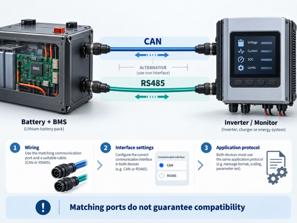
CAN or UART support does not establish compatibility with a proprietary system.
Specify the bicycle’s response when data is missing, stale or invalid.
10. Specify the Battery–Charger Combination
The charger must match the selected battery’s charging requirements.
Define:
Charging voltage and tolerance.
Charging current.
Charge termination behavior.
Charging temperature limits.
Connector and polarity.
Communication or identification requirements.
Fault response.
Connector fit and nominal voltage alone are insufficient. For example, Bosch’s guidance identifies system-specific charger compatibility, including software requirements. That guidance applies to Bosch systems and should not be treated as a specification for unrelated products. Source: Bosch Charger Compatibility Guidance
Validate charging time under stated conditions. Dividing capacity by charging current does not account for the complete charging profile.
11. Document Environmental Requirements
Identify the conditions the assembled pack will encounter:
Riding and charging temperatures.
Storage temperature and duration.
Rain and splash exposure.
Cleaning methods.
Dust and contamination.
Vibration and shock.
Solar heating.
Airflow around the installed pack.
If an ingress protection rating is required, define the tested assembly, including connectors, covers and openings.
Measure component temperatures during representative riding and charging. Ambient temperature alone does not establish cell temperature.
12. State Cycle-Life Test Conditions
A cycle-life claim needs a defined test method and endpoint.
Document:
Charge and discharge rates.
Depth of discharge.
Temperature.
Capacity retention endpoint.
Calendar-life requirements.
Energy required at the service endpoint.
Do not present a laboratory cycle count as a guaranteed field service period.
Define replacement compatibility for mounting, connectors, charger and communication.
13. Confirm Assessment and Documentation Scope
Battery testing, complete e-bike assessment and transport testing serve different purposes.
UL 2271 and UL 2849
UL 2271 addresses batteries for light electric vehicle applications. UL 2849 addresses e-bike electrical systems, including the relevant drivetrain, battery and charger combination.
Battery certification does not establish certification of the complete bicycle electrical system. Confirm applicable requirements for the destination market. Source: UL Solutions E-Bike Certification
UN38.3
Lithium battery transport involves applicable UN38.3 testing and test summary requirements.
The documentation should correspond to the battery design being supplied. Transport testing does not replace product safety assessment. Source: PHMSA Lithium Battery Test Summaries
Check the Actual Documents
Verify:
Product model.
Manufacturing site.
Certificate holder.
Standard edition.
Covered construction.
Document status.
Use certification marks only under the relevant authorization. Testing to a standard does not, by itself, authorize use of a certification logo.
14. Establish a System Validation Plan
Test the battery with the intended controller, charger, display and mounting system.
| Test Area | Verification |
|---|---|
| Electrical operation | Voltage range, current demand and sequencing |
| Riding performance | Energy consumption under defined conditions |
| Thermal behavior | Cell and component temperatures |
| Charging | Profile, termination and fault handling |
| Communication | Interpretation, timing and timeout behavior |
| Mechanical integration | Fit, retention and removal |
| Connectors | Contact behavior and insertion cycles |
| Environmental exposure | Defined ingress, vibration and shock tests |
| Protection | Response and recovery under specified faults |
Set acceptance criteria before testing. Record hardware revisions, firmware versions, equipment and test conditions.
Bench operation alone does not establish performance in the installed bicycle.
15. OEM Battery RFQ Checklist
| Category | Information to Provide |
|---|---|
| Application | Bicycle type, loads and riding conditions |
| Electrical | Controller specification and voltage range |
| Energy | Capacity, test conditions and usable energy target |
| Current | Continuous and transient current profiles |
| Charging | Charger specification and charging schedule |
| Mechanical | Drawings, mounting and mass limits |
| Interfaces | Connectors, wiring and communication |
| BMS | Monitoring, protection and recovery behavior |
| Environment | Temperature, moisture, vibration and storage |
| Service life | Test conditions and replacement criteria |
| Compliance | Destination markets and document requirements |
| Validation | Tests, acceptance criteria and responsibilities |
| Production | Quantities, traceability and change control |
Ask the supplier to identify assumptions and unresolved requirements.
Frequently Asked Questions
Is a 48V Battery Compatible With Every 48V E-Bike?
No. Charging voltage, current limits, connectors, mounting, communication and charger requirements must also match.
Does Capacity Determine Riding Range?
Capacity contributes to available energy. Riding range also depends on consumption and operating conditions.
Can Different Cells Be Used in the Same Enclosure?
Possibly. Each change requires review of performance, construction and document coverage.
Does Battery Certification Cover the Complete E-Bike?
Not automatically. The battery and e-bike electrical system have different assessment scopes.
What Should Be Approved Before Production?
Approve the construction, cell model, BMS settings, firmware, charger, interfaces, validation results and required documentation.
Preparing the Project Specification
Begin with the bicycle’s electrical requirements and installation drawings. Document energy demand, current, charging, communication and operating conditions.
Establish an approved specification and validate the battery with the intended e-bike system before production.
Related articles


-
2026-09-22
How to Customize a Robot Battery Pack...

 E-mail


 +86 13510702894