



CAN Communication in Lithium Battery Packs for AGVs and AMRs
Automated Guided Vehicles (AGVs) and Autonomous Mobile Robots (AMRs) use lithium battery packs to power their motors, controllers, sensors, and electrical components.
During operation, the equipment controller may need information about battery voltage, current, State of Charge (SOC), temperature, and fault status.
CAN communication in lithium battery packs provides a data interface between the Battery Management System (BMS) and the equipment controller.
For custom AGV and AMR battery projects, communication requirements should be defined during the battery development stage. The interface, message format, electrical parameters, and connector configuration need to be compatible with the customer's equipment.
This article explains how CAN communication is used in AGV and AMR lithium battery packs, the information that may be transmitted by a BMS, and the specifications required for battery customization.
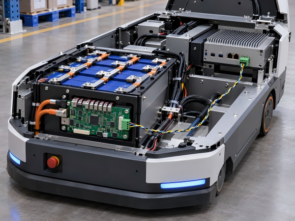
1. What Is CAN Communication in a Lithium Battery Pack?
CAN stands for Controller Area Network. It is a communication technology used to exchange data between electronic control units.
CAN is used in vehicles, industrial equipment, automation systems, and robotics.
In a lithium battery pack, a BMS equipped with a CAN interface can transmit defined battery operating information to an external controller.
Depending on the BMS configuration, the transmitted information may include:
Total battery voltage
Battery current
State of Charge (SOC)
State of Health (SOH), where implemented
Cell voltage information
Battery temperature
Charging and discharging status
BMS protection status
Fault information
The equipment controller receives and processes this information according to the agreed communication protocol.
For example, an AMR controller may use SOC information as an input for charging schedules and task management.
CAN provides a communication interface. The actual battery functions depend on the BMS hardware, firmware, and system design.
2. CAN Communication Applications in AGVs and AMRs
AGVs and AMRs operate according to programmed movement, task scheduling, and power management requirements.
Battery monitoring can be integrated into the equipment control system through CAN communication.
Battery Status Monitoring
CAN communication allows an equipment controller to receive battery operating information.
Depending on the BMS functions, the controller may display:
Battery voltage
Battery current
SOC
Battery temperature
Fault status
The available information is determined by the BMS configuration and communication protocol.
SOC Monitoring
State of Charge (SOC) represents an estimate of the battery's remaining charge relative to its defined capacity.
An AGV or AMR may use SOC information to support charging schedules and operating decisions.
SOC estimation depends on the BMS measurement method, firmware, and battery parameters.
Fault Information Reporting
A BMS may report defined fault conditions through CAN communication.
Examples include:
Cell overvoltage
Cell undervoltage
Battery overcurrent
Battery over-temperature
Battery under-temperature
Temperature sensor fault
The equipment controller processes the reported information according to its software configuration.
Equipment Integration
CAN communication allows battery information to be exchanged between the BMS and the equipment controller.
The communication interface and required data should be confirmed before prototype development.
3. Battery Information Transmitted Through CAN
Different BMS models support different data monitoring functions.
The following table provides examples of battery information that may be included in a CAN protocol.
| Battery Parameter | Description | Application |
|---|---|---|
| Total Voltage | Battery pack voltage | Battery status monitoring |
| Battery Current | Charging or discharging current | Load monitoring |
| SOC | Estimated remaining charge | Charging and task scheduling |
| SOH | Estimated battery health, where implemented | Battery condition monitoring |
| Cell Voltage | Series-connected cell group voltage | Diagnostic monitoring |
| Battery Temperature | Temperature sensor readings | Thermal monitoring |
| Charge Status | Reported charging condition | Charging status monitoring |
| Discharge Status | Reported discharge condition | Equipment status monitoring |
| Fault Codes | Defined BMS fault information | Equipment diagnostics |
| BMS Status | Defined BMS operating state | System monitoring |
The available data depends on the selected BMS hardware, firmware, and communication protocol.
A CAN interface does not automatically mean that every parameter in this table is available.
4. CAN Communication and BMS Protection Functions
The Battery Management System monitors electrical and temperature conditions according to its hardware and firmware configuration.
Depending on the BMS design, protection functions may include:
Overcharge protection
Over-discharge protection
Overcurrent protection
Short-circuit protection
Charging over-temperature protection
Discharging over-temperature protection
Low-temperature charging protection
Cell balancing
These functions operate according to the BMS circuit design and protection settings.
CAN communication can transmit battery information and protection status to the equipment controller.
Does CAN Control Battery Charging and Discharging?
CAN communication does not automatically provide control over battery charging or discharging.
In a monitoring-only configuration, CAN is used to transmit battery operating information.
Charging and discharging functions are managed through the battery's electrical circuits, BMS protection system, and connected equipment.
For example, a battery pack may use a separate discharge enable switch connected to designated pins.
In this configuration, the discharge function depends on the switch circuit rather than a CAN command.
Some battery systems use CAN-based charging requests or control messages. Such functions require compatible hardware, firmware, and defined communication protocols.
For OEM projects, customers should confirm whether CAN is required for battery data monitoring or whether additional control functions are specified.
5. CAN Bus Interface and Wiring Requirements
The CAN interface is part of the battery pack's electrical design.
CAN communication commonly uses a differential signal pair:
CAN_H
CAN_L
Depending on the system design, the connector may also include signal reference, shielding, or other connections.
CAN Connector Selection
Battery CAN interfaces may use:
Circular industrial connectors
Multi-pin connectors
Waterproof connectors
Customized signal connectors
Combined power and signal connectors
Connector selection depends on the equipment's installation requirements, pin assignments, operating environment, and mechanical structure.
CAN Bus Termination
High-speed Classical CAN networks commonly use 120Ω termination resistors at the two physical ends of the bus.
The termination arrangement depends on the network topology and transceiver design.
Termination resistors should not be added to every device without evaluating the complete network.
For a custom battery pack, the customer and battery manufacturer should confirm whether CAN termination is located inside the BMS, in the cable assembly, or within the equipment.
CAN Cable Routing
CAN wiring design may consider:
Twisted-pair signal wiring
Cable length
Connector pin assignments
Network topology
Signal reference
Electromagnetic interference
Shielding requirements
Wiring requirements should follow the selected CAN physical-layer specification and equipment design.
6. CAN Communication Protocol Requirements
A CAN connection defines the data transmission interface but does not determine the meaning of the battery information.
The BMS and equipment controller must use compatible communication protocols.
The protocol defines message structure, identifiers, data interpretation, and communication behavior.
CAN Bit Rate
The communication bit rate must match the network configuration.
Examples of Classical CAN bit rates include:
125 kbit/s
250 kbit/s
500 kbit/s
These values are examples rather than specifications of a particular First Power battery pack.
The actual bit rate depends on the selected BMS and customer requirements.
CAN Message Identifiers
CAN messages use identifiers to distinguish transmitted frames and support bus arbitration.
A battery communication protocol may specify:
CAN identifier
Message direction
Data length
Signal definition
Transmission interval
Data scaling factor
Data offset
Data type
Byte order
Battery Data Format
Battery information is transmitted according to the agreed protocol format.
For example, battery voltage may be represented by a numerical value and scaling factor.
The equipment controller must interpret the transmitted value according to the protocol documentation.
Message Transmission Interval
Battery information may be transmitted periodically or according to defined request and event conditions.
The required transmission interval should be confirmed during system integration.
7. CANopen and Custom CAN Protocols
Battery communication systems may use standardized higher-layer protocols or application-specific message definitions.
CANopen
CANopen is a CAN-based higher-layer communication system used in industrial automation and embedded control applications.
It defines communication mechanisms, object dictionaries, and network management functions.
CAN in Automation (CiA) publishes communication specifications and device profiles for different applications.
Support for CANopen requires implementation of the applicable protocol requirements.
Custom CAN Protocols
Some AGV and AMR manufacturers use application-specific CAN protocols.
These protocols may define:
Custom CAN identifiers
Data fields
Transmission intervals
Fault codes
Battery status messages
For a custom battery project, the customer should provide the communication protocol or interface requirements.
The battery manufacturer can then evaluate the selected BMS against the protocol specifications.
A BMS equipped with a CAN interface is not automatically compatible with CANopen or a proprietary CAN protocol.
Protocol compatibility requires technical evaluation and testing.
8. CAN Communication in 48V-Class AGV and AMR Battery Packs
48V-class lithium battery packs are used in certain industrial robot, AGV, and AMR applications.
The actual battery configuration depends on the cell chemistry and equipment voltage requirements.
Examples include:
| Battery Chemistry | Configuration | Typical Nominal Voltage |
|---|---|---|
| Ternary Lithium-Ion | 13S | 46.8V |
| Ternary Lithium-Ion | 14S | 50.4V |
| LiFePO4 | 15S | 48.0V |
| LiFePO4 | 16S | 51.2V |
The nominal voltages shown are calculated using typical cell nominal voltage values.
Actual charging and discharging voltage ranges depend on the selected cell specifications.
Example AGV Battery Requirements
The following table provides an illustrative example of a custom AGV battery project.
| Parameter | Example Specification |
|---|---|
| Battery Chemistry | LiFePO4 |
| Nominal Voltage | 51.2V |
| Battery Capacity | 50Ah |
| Communication Interface | CAN |
| Communication Function | Battery status monitoring |
| Required Data | Voltage, current, SOC, temperature, fault status |
| Continuous Discharge Current | According to equipment load |
| Peak Discharge Current | According to operating requirements |
| Connector | According to equipment interface |
| BMS Protection | According to approved specifications |
These values are examples for explaining the design process and do not represent an existing production battery model.
The CAN communication interface must be evaluated together with the electrical and mechanical requirements.
9. CAN Communication and Battery Charging Systems
AGVs and AMRs may use charging connectors or automated charging stations.
Battery charging requirements may include:
Charger output voltage
Charger output current
Charging connector
Charging temperature limits
Charging status monitoring
Communication compatibility
Charging station integration
A battery pack equipped with CAN communication does not automatically require a CAN-controlled charger.
Some charging systems operate according to defined electrical charging parameters.
Other systems may require communication between the battery, charger, and equipment controller.
If charger communication is required, customers should provide the communication protocol and charger specifications.
Charging current control responsibilities should be defined according to the charger, BMS, and equipment system architecture.
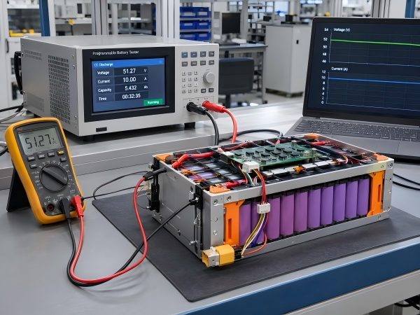
10. CAN Communication Testing During Battery Pack Development
CAN communication can be evaluated during prototype development and equipment integration.
The testing scope depends on the approved BMS configuration and communication protocol.
Physical Interface Verification
Testing may include:
CAN_H and CAN_L wiring inspection
Connector pin verification
CAN bit rate confirmation
Termination configuration inspection
Communication signal evaluation
Data Verification
Testing may include:
Battery voltage reporting
Current reporting
SOC reporting
Temperature reporting
Fault status reporting
Message transmission intervals
The reported values should be evaluated according to the measurement method and protocol definitions.
Fault Reporting Verification
Defined fault conditions may be evaluated according to an approved test procedure.
Testing should verify the transmitted fault information and corresponding BMS status.
Equipment Integration Testing
The battery may require communication testing with the customer's equipment controller.
Integration testing may include:
Equipment startup
CAN message reception
Battery status display
Communication interruption handling
Charging status reporting
Fault information processing
Testing should follow the agreed interface specifications.
11. CAN Integration Issues in AGV and AMR Battery Systems
Communication issues may occur because of wiring, network configuration, or protocol differences.
CAN Bit Rate Mismatch
Communication may fail if the BMS and equipment controller use incompatible bit rates.
CAN_H and CAN_L Wiring
Incorrect pin assignments or wiring can interrupt communication.
Termination Configuration
Incorrect termination arrangements may contribute to signal reflections and communication errors.
CAN Identifier Mismatch
The equipment controller may expect message identifiers that differ from those transmitted by the BMS.
Data Scaling and Byte Order
Voltage, current, or temperature values may be interpreted incorrectly if the communication protocol uses inconsistent scaling factors, offsets, or byte order.
Message Timing
The equipment controller may require battery messages at defined intervals.
Timing requirements should be included in the protocol specification.
Communication Interruption
The equipment system should define how it responds when battery communication is interrupted.
The response depends on the equipment control architecture and applicable safety requirements.
12. Information Required for a Custom CAN BMS Battery Pack
OEM customers developing AGV or AMR battery packs with CAN communication should provide the following information.
1. Battery Specifications
Nominal voltage, capacity, chemistry, and operating voltage range.
2. Discharge Requirements
Continuous discharge current, peak discharge current, and peak duration.
3. CAN Communication Requirements
CAN bit rate
CAN identifier format
Communication protocol
Required battery data
Transmission intervals
Fault reporting requirements
4. BMS Requirements
Protection functions, temperature monitoring, cell balancing, and required data reporting.
5. Charging Requirements
Charging voltage, charging current, charging connector, and communication requirements.
6. Connector Requirements
Connector model, pin assignments, cable length, and installation position.
7. Mechanical Requirements
Battery dimensions, mounting positions, enclosure material, and installation drawings.
8. Operating Conditions
Operating temperature, environmental protection, vibration exposure, and duty cycle.
9. Production Requirements
Prototype quantity, production forecast, target market, and applicable standards.
These details are used to evaluate the battery configuration, BMS requirements, and communication interface.
13. Custom AGV and AMR Battery Packs at First Power
First Power provides OEM and ODM custom lithium battery pack development and manufacturing services.
Our battery pack business covers electric mobility, robotics, industrial equipment, and energy storage applications.
Our customization scope includes:
Ternary lithium-ion and LiFePO4 battery pack configurations
Customized voltage and capacity
Battery cell selection
BMS configuration according to project requirements
CAN, UART, and RS485 communication options
NTC temperature monitoring
Customized charging and discharging connectors
Plastic and aluminum battery enclosures
Battery pack assembly
Technical documentation and project testing coordination
For AGV and AMR battery projects, electrical specifications, communication requirements, mechanical dimensions, and operating conditions are considered during technical evaluation.
CAN communication functions depend on the selected BMS hardware, firmware, and agreed protocol.
The final battery design is determined according to the confirmed project specifications.
Conclusion
CAN communication provides a data interface between lithium battery packs and AGV or AMR equipment controllers.
Through a compatible BMS and communication protocol, the equipment controller can receive defined battery information, including voltage, current, SOC, temperature, and fault status.
CAN communication requirements should be confirmed together with battery voltage, capacity, discharge current, charging specifications, and mechanical dimensions.
The interface, protocol, connector wiring, and equipment integration requirements form part of the battery development process.
Developing a custom lithium battery pack with CAN communication for an AGV or AMR?
Contact First Power with your battery specifications, communication protocol, mechanical drawings, and estimated order quantity.
Our team can review the project requirements and discuss battery configuration and CAN communication options.

 E-mail



 +86 13510702894
