



Marine Lithium Battery Pack Design: Electrical and Environmental Requirements
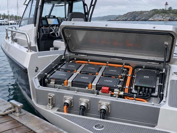
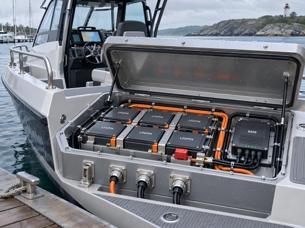
Marine lithium battery packs are used in electric boats, marine auxiliary power systems, onboard equipment, and battery-powered monitoring devices.
Battery systems installed in marine environments may be exposed to electrical loads, vibration, humidity, salt-containing air, and water contact. These conditions influence battery cell selection, Battery Management System (BMS) requirements, enclosure construction, electrical connections, and installation methods.
For OEM and ODM projects, marine lithium battery pack design begins with evaluating the equipment's electrical requirements and installation environment.
A battery installed in an enclosed cabin and a battery exposed to water spray may require separate environmental protection specifications.
This article explains the electrical, mechanical, and environmental considerations involved in custom marine lithium battery pack development.
1. Applications of Marine Lithium Battery Packs
Lithium batteries are used in marine equipment with various electrical and operating requirements.
Electric Boat Propulsion Systems
Electric propulsion systems use batteries to supply electrical power to motors and motor controllers.
Battery requirements depend on propulsion power, operating voltage, current demand, vessel operating conditions, and required runtime.
Marine Auxiliary Power Systems
Auxiliary battery systems may supply power to onboard electrical equipment, lighting, control systems, and other approved loads.
The battery configuration depends on the vessel's electrical architecture and power consumption.
Marine Monitoring Equipment
Marine monitoring systems may require battery packs for sensors, communication devices, navigation-related equipment, and environmental monitoring instruments.
These applications may involve compact enclosures and environmental protection requirements.
Marine Industrial Equipment
Battery-powered marine equipment may operate on vessels, in ports, or in coastal industrial environments.
Battery design should consider electrical demand, mechanical installation, humidity, and corrosion exposure.
Each application requires evaluation of the battery's operating conditions and system integration requirements.
2. Selecting Battery Voltage for Marine Applications
Battery voltage is a basic parameter in marine lithium battery design.
The required voltage depends on the electrical system, connected equipment, motor controller, and charging arrangement.
Examples of voltage classes used in marine electrical equipment include:
12V
24V
36V
48V
The actual battery voltage depends on cell chemistry and series configuration.
LiFePO4 Battery Voltage Configurations
LiFePO4 cells typically have a nominal voltage of 3.2V per cell.
Examples include:
| Configuration | Nominal Voltage | Application Voltage Class |
|---|---|---|
| 4S LiFePO4 | 12.8V | 12V class |
| 8S LiFePO4 | 25.6V | 24V class |
| 12S LiFePO4 | 38.4V | Application-dependent |
| 15S LiFePO4 | 48.0V | 48V class |
| 16S LiFePO4 | 51.2V | Subject to equipment compatibility |
These configurations are illustrative calculations and do not represent specific production battery models.
The equipment manufacturer should confirm:
Nominal operating voltage
Permitted voltage range
Maximum charging voltage
Minimum operating voltage
Motor controller compatibility
Charger requirements
A nominal voltage label alone does not establish electrical compatibility.
3. Battery Capacity and Energy Requirements
Battery capacity is expressed in ampere-hours (Ah), while energy is expressed in watt-hours (Wh) or kilowatt-hours (kWh).
The required battery capacity depends on the equipment's power consumption and operating duration.
Battery Energy Calculation
Nominal battery energy can be calculated using:
Energy (Wh) = Nominal Voltage (V) × Capacity (Ah)
For example, a theoretical battery pack with:
Nominal voltage: 25.6V
Capacity: 100Ah
Has a nominal energy of:
25.6V × 100Ah = 2,560Wh = 2.56kWh
This is an illustrative calculation, not a specification of an existing product.
Factors Affecting Battery Capacity
Marine battery sizing should consider:
Electrical power consumption
Operating duration
Motor load
Auxiliary equipment demand
Charging intervals
Operating temperature
Usable battery energy
Equipment duty cycle
Required energy reserve
For electric propulsion applications, current demand may change with vessel speed, propeller load, and operating conditions.
Battery capacity should be calculated using the expected operating profile and required energy.
4. Continuous and Peak Discharge Current
Marine battery packs must support the electrical current required by connected equipment.
Continuous and peak discharge current should be specified separately.
Continuous Discharge Current
Continuous discharge current describes the current required during sustained operation.
This parameter affects:
Battery cell selection
Parallel cell configuration
BMS current rating
Busbar design
Cable selection
Connector specifications
Thermal management
Peak Discharge Current
Peak discharge current refers to the current required for a defined short-duration operating condition.
Peak current may occur during motor startup, acceleration, or changes in equipment load.
An illustrative battery project may have the following requirements:
| Parameter | Example Requirement |
|---|---|
| Nominal Voltage | 25.6V |
| Capacity | 100Ah |
| Continuous Discharge Current | 50A |
| Peak Discharge Current | 100A |
| Peak Duration | 5 seconds |
These values are engineering examples and do not represent a verified marine battery model.
The actual current requirements must be evaluated using equipment specifications and the selected cell manufacturer's documentation.
Peak current duration and repetition frequency should be included in the technical requirements.
5. LiFePO4 Cell Selection for Marine Battery Packs
Lithium Iron Phosphate (LiFePO4) is a lithium battery chemistry used in marine auxiliary power, electric propulsion, and industrial energy storage applications.
Cell selection should be based on the battery's electrical and environmental requirements.
Cell Selection Parameters
Relevant specifications include:
Nominal voltage
Rated capacity
Continuous discharge current
Pulse discharge capability
Internal resistance
Charging current
Operating temperature
Cycle life specification
Cell dimensions
Terminal configuration
Prismatic and cylindrical lithium battery cells have distinct mechanical and electrical connection structures.
The selected cell model should be evaluated against the required battery enclosure, installation conditions, and electrical load.
Cell Configuration
Series connections determine battery voltage.
Parallel connections determine combined battery capacity and contribute to current capability.
The final configuration must account for electrical insulation, cell mounting, current paths, and thermal conditions.
Cell chemistry and cell format alone do not establish the complete battery pack's suitability for marine applications.
6. BMS Requirements for Marine Lithium Batteries
The Battery Management System monitors electrical and thermal conditions according to its hardware and software configuration.
A custom marine battery pack may require BMS functions such as:
Cell voltage monitoring
Overcharge protection
Over-discharge protection
Overcurrent protection
Short-circuit protection
Temperature monitoring
Low-temperature charging protection
Cell balancing
Fault reporting
The required functions depend on the battery application and system design.
Current Protection
The BMS current rating should be evaluated against the continuous and peak current requirements.
Electrical connections, protection devices, and thermal conditions must also be considered.
Temperature Monitoring
Temperature sensors may be positioned near selected cells or electrical components according to the thermal design.
The number of sensors and protection thresholds should be defined during development.
SOC and SOH Monitoring
Some projects require State of Charge (SOC) or State of Health (SOH) information.
These functions depend on BMS hardware, measurement methods, firmware, and battery configuration.
The availability and required accuracy of reported data should be included in the project specification.
7. CAN Communication and Marine Battery Monitoring
Marine electrical systems may require battery operating information to be transmitted to external equipment.
Depending on the project, communication interfaces may include CAN, UART, or RS485.
A CAN-equipped BMS can transmit defined battery data according to an agreed protocol.
Examples include:
Battery voltage
Battery current
SOC
Temperature
Protection status
Fault information
CAN Protocol Requirements
Customers should provide:
CAN bit rate
CAN identifiers
Message format
Required data
Transmission intervals
Connector pin assignments
Marine equipment may use specific communication protocols, including CAN-based vessel networks.
A CAN-enabled BMS is not automatically compatible with NMEA 2000 or another marine communication protocol.
Compatibility requires evaluation of the physical interface, protocol implementation, and connected equipment.
CAN Monitoring and Control
In a monitoring-only configuration, CAN is used to transmit battery information.
CAN communication does not automatically control battery charging or discharging.
Additional control functions require compatible hardware, firmware, and system integration.
8. Charging System Requirements
Charging system compatibility is part of marine battery pack design.
A marine battery may be connected to a dedicated charger, shore-power charging system, DC-DC charger, or another approved charging source.
The charging arrangement should be defined before battery development.
Charging Voltage and Current
The charger must provide a charging profile compatible with the selected cells and battery configuration.
Required parameters include:
Charging voltage
Charging current
Charging termination conditions
Charging temperature limits
Charger communication requirements, where applicable
Charging Source Compatibility
Marine charging systems may involve alternators, DC-DC converters, shore-power chargers, or renewable energy charging equipment.
The charging source must be evaluated for compatibility with the BMS and battery's electrical limits.
BMS Protection and Charging Disconnect
A BMS protection event may interrupt charging.
The charging system should be designed to respond to battery protection events without creating hazards in the connected electrical system.
Systems involving engine-driven alternators may require charging control and electrical protection arrangements.
The battery manufacturer and marine electrical system designer should define the charging interface and protection responsibilities.
9. Waterproof Enclosure and IP Rating Requirements
Water exposure is an environmental consideration in marine battery pack design.
Depending on the installation location, battery enclosures may be exposed to water splashes, rain, condensation, or temporary immersion.
The required enclosure protection should be established according to the application.
Understanding IP Ratings
Ingress Protection (IP) ratings are defined by IEC 60529.
Examples include:
| IP Rating | Protection Description |
|---|---|
| IP54 | Dust-protected and protected against splashing water |
| IP65 | Dust-tight and protected against water jets |
| IP67 | Dust-tight and protected against temporary immersion |
| IP68 | Dust-tight and protected against immersion under specified conditions |
The specified rating must be verified according to the applicable test requirements.
IP67 does not automatically establish suitability for sustained underwater operation.
IP68 conditions must be defined according to immersion depth, duration, and relevant product requirements.
Enclosure Sealing
Marine battery enclosures may require:
Sealing gaskets
Protected housing joints
Sealed cable outlets
Waterproof connectors
Cable glands
Enclosure materials selected for the environment
The sealing design should consider the complete battery assembly.
A connector's individual IP rating does not establish the IP rating of the complete battery pack.
Condensation
Temperature changes and humidity may cause condensation inside an enclosure.
Enclosure design should consider moisture accumulation, insulation, material compatibility, and the installation environment.
A sealed enclosure does not automatically eliminate condensation.
10. Salt Spray and Corrosion Protection
Marine environments may expose battery enclosures and electrical connections to salt-containing moisture.
Salt deposits and moisture can contribute to corrosion and electrical insulation problems.
Design considerations include:
Enclosure material
Surface treatment
Connector material
Terminal protection
Fastener material
Cable sealing
Corrosion protection of exposed metal components
Electrical isolation between dissimilar metals
Metal Enclosures
Aluminum and other metal enclosures may be considered according to project requirements.
Surface treatments and material compatibility should be evaluated for the intended environment.
Connectors and Terminals
Electrical connectors should be selected according to the specified environment and operating conditions.
Contact materials, sealing structures, and cable termination methods should be included in the evaluation.
Salt Spray Testing
Where required, corrosion resistance may be evaluated using an applicable salt spray or cyclic salt mist test method.
The test specification, exposure conditions, duration, and acceptance criteria should be agreed upon for the project.
An IP rating does not establish resistance to salt corrosion.
11. Mechanical Design and Battery Installation
Marine battery packs require mechanical support appropriate for their installation environment.
The design should account for vessel movement, vibration, inclination, and mounting conditions.
Battery Compartment Requirements
Customers should provide:
Available installation dimensions
Mounting orientation
Mounting points
Battery mass requirements
Connector positions
Cable routing
Maintenance access
Environmental exposure
Mechanical Retention
The battery should be secured according to the applicable installation requirements.
Mounting structures should account for specified vibration, movement, and mechanical loads.
The design should consider battery retention and prevention of unintended movement during vessel operation.
Electrical Protection
Electrical terminals and current-carrying components should be protected against unintended contact and short circuits.
System-level protection may include suitable fuses, circuit breakers, isolation devices, and electrical wiring arrangements.
The selection and installation of these components should follow the applicable marine electrical system requirements.
12. Thermal Management in Marine Battery Packs
Lithium battery cells and electrical components generate heat during charging and discharging.
Thermal performance depends on:
Battery cell chemistry
Internal resistance
Continuous current
Peak current duration
Charging current
Cell arrangement
Enclosure structure
Ambient temperature
Available heat dissipation paths
Sealed Battery Enclosures
A sealed enclosure restricts air exchange with the surrounding environment.
Thermal design should account for heat generated during the intended operating cycle.
Depending on the application, thermal management may involve conductive heat transfer paths, enclosure design, or application-specific cooling methods.
Temperature Protection
BMS temperature monitoring and protection settings should follow the approved battery design and cell manufacturer's specifications.
Charging and discharging temperature limits must be considered separately.
Abnormal Conditions
Marine battery system design should also address abnormal heating, electrical faults, cell failure, and other relevant safety conditions.
Depending on system energy and installation requirements, ventilation, gas management, fire protection, and thermal propagation evaluation may form part of the vessel-level safety assessment.
An enclosure IP rating does not replace these safety assessments.
13. Marine Battery Testing and Applicable Standards
Marine lithium battery projects may involve electrical, mechanical, thermal, environmental, and regulatory requirements.
The applicable standards depend on the vessel type, battery application, operating area, system energy, and certification scope.
Examples include:
| Standard / Requirement | Application or Purpose |
|---|---|
| UN38.3 | Lithium battery transportation testing |
| IEC 62619 | Safety requirements for industrial secondary lithium cells and batteries |
| IEC 60529 | Ingress protection classification |
| IEC 60092-507 | Electrical installation requirements for applicable small vessels |
| ABYC E-13 | Lithium-ion battery selection, installation, and system requirements for covered boat applications |
| ABS Marine Battery Requirements | Lithium-ion battery systems within the applicable marine classification scope |
These references are not interchangeable certifications. Their applicability must be assessed for each project.
Electrical Validation
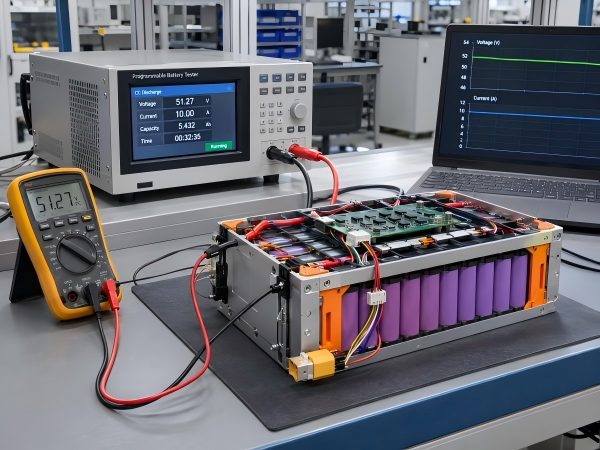
Testing may include:
Battery voltage verification
Capacity testing
Charging and discharging evaluation
Continuous current testing
Peak current testing
BMS protection verification
Environmental Validation
Depending on project requirements, testing may include:
Water ingress testing
Humidity exposure
Salt spray or cyclic corrosion testing
Temperature testing
Vibration testing
Mechanical Validation
Mechanical verification may include:
Enclosure dimensions
Mounting structure
Connector installation
Battery retention
Cable routing
Mechanical integrity
Certification and Classification
Engineering validation does not automatically establish compliance with marine electrical regulations or classification society requirements.
Where marine type approval, vessel certification, or classification is required, the scope should be confirmed with the relevant authority or certification body.
14. Information Required for a Custom Marine Lithium Battery Quotation
OEM customers requesting a custom marine lithium battery pack should provide the following information.
| Item | Required Information |
|---|---|
| Application | Electric boat, auxiliary power, monitoring equipment or other marine use |
| Vessel / Equipment Type | Equipment model and operating function |
| Battery Chemistry | LiFePO4 or specified chemistry |
| Nominal Voltage | Required voltage |
| Battery Capacity | Ah or Wh |
| Continuous Discharge Current | A |
| Peak Discharge Current | A and duration |
| Charging Requirements | Charging voltage, current and charging source |
| Battery Dimensions | Maximum length × width × height |
| Installation Position | Compartment location and mounting orientation |
| Enclosure Material | Plastic, aluminum or specified material |
| IP Rating | Required protection level, where applicable |
| Corrosion Requirements | Salt exposure, material and testing requirements |
| BMS Requirements | Protection, monitoring and balancing functions |
| Communication | CAN, UART, RS485 or specified protocol |
| Connectors | Charging, discharging and signal interfaces |
| Operating Temperature | Charging and discharging ranges |
| Mechanical Conditions | Vibration, movement and mounting requirements |
| Standards | Required market, vessel and certification standards |
| Prototype Quantity | Sample quantity |
| Production Forecast | Estimated order quantity |
| Delivery Destination | Country and address |
For marine installations, customers should also provide relevant electrical system drawings and battery compartment specifications.
If a classification society or vessel certification authority is involved, the applicable requirements should be confirmed during project planning.
15. Custom Lithium Battery Pack Development at Firstpower
Firstpower provides OEM and ODM custom lithium battery pack development and manufacturing services for electric mobility, robotics, industrial equipment, and energy storage applications.
For marine-related battery inquiries, the project can be evaluated according to its electrical specifications, environmental requirements, mechanical dimensions, and integration conditions.
Our customization scope includes:
LiFePO4 and ternary lithium-ion battery configurations
Customized voltage and capacity
Battery cell selection
BMS configuration according to project requirements
CAN, UART and RS485 communication options
NTC temperature monitoring
Customized connectors and wiring
Plastic and metal enclosure development
Battery pack assembly
Technical documentation and project testing coordination
Marine-specific requirements, including water ingress protection, corrosion exposure, installation conditions, and applicable standards, must be evaluated according to the individual project.
The final design and testing scope depend on the confirmed requirements and component specifications.
Conclusion
Marine lithium battery pack design involves electrical, mechanical, thermal, and environmental requirements.
Battery voltage, capacity, continuous discharge current, peak current, BMS protection, charging compatibility, and communication interfaces determine the electrical design requirements.
Water exposure, humidity, salt-containing environments, vibration, and installation conditions influence enclosure materials, sealing structures, connectors, and mechanical support.
For OEM and ODM marine battery projects, technical specifications should be confirmed before selecting the battery configuration and enclosure structure.
Looking for a custom lithium battery pack for marine equipment?
Contact Firstpower with your battery specifications, operating environment, mechanical drawings, BMS requirements, and estimated production quantity.
Our team can review the project requirements and discuss a battery pack configuration based on your application.
Website: www.szfirstpower.com
Email: joy.yu@szfirstpower.com

 E-mail



 +86 13510702894
